Lincoln Aviator 2020-2024 Service Manual / Electrical / Battery and Charging System / Voltage Converter/Inverter / Description and Operation - Direct Current/Alternating Current (DC/AC) Inverter - Plug-In Hybrid Electric Vehicle (PHEV) - Component Location
Lincoln Aviator: Voltage Converter/Inverter / Description and Operation - Direct Current/Alternating Current (DC/AC) Inverter - Plug-In Hybrid Electric Vehicle (PHEV) - Component Location
.jpg)
| Item | Description |
|---|---|
| 1 | AC Power Outlet Socket |
| 2 | Direct Current/Alternating Current (DC/AC) Inverter |
 Description and Operation - Direct Current/Alternating Current (DC/AC) Inverter - System Operation and Component Description
System Diagram
System Operation
Network Message Chart
Broadcast Message
Originating Module
Message Purpose
Power pack torque status
Secondary On-Board Diagnostic Control Module C (SOBDMC)
Used to determine if the vehicle is started or if torque is available...
Other information:
Lincoln Aviator 2020-2024 Service Manual: Removal and Installation - Remote Keyless Entry (RKE) Exterior Sounder
Removal Remove the air cleaner intake pipe. Refer to: Air Cleaner Intake Pipe (303-12 Intake Air Distribution and Filtering - 3.0L EcoBoost/3.0L EcoBoost – Hybrid (BQ), Removal and Installation). Remove the CAC outlet pipe. Refer to: Charge Air Cooler (CAC) Outlet Pipe (303-12 Intake Air Distribution and Filtering - 3...
Lincoln Aviator 2020-2024 Service Manual: Removal and Installation - Second Row Single Seat Backrest Cover - Vehicles With: Second Row Captain Chairs
Special Tool(s) / General Equipment Interior Trim Remover Removal NOTE: LH (left hand) seat shown, RH (right hand) seat similar. Remove the second row seat. Refer to: Second Row Seat - Vehicles With: Second Row Captain Chairs (501-10B Second Row Seats, Removal and Installation)...
Categories
- Manuals Home
- Lincoln Aviator Owners Manual
- Lincoln Aviator Service Manual
- Changing the Front Wiper Blades - Vehicles With: Heated Wiper Blades
- Wireless Accessory Charger (If Equipped)
- Garage Door Opener
- New on site
- Most important about car
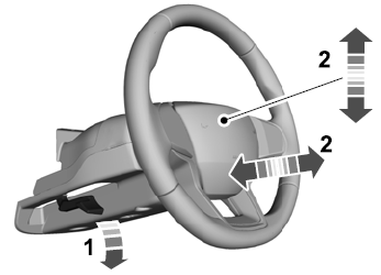
Adjusting the Steering Wheel - Vehicles With: Manual Adjustable Steering Column
WARNING: Do not adjust the steering wheel when your vehicle is moving.
Note: Make sure that you are sitting in the correct position.
Unlock the steering column. Adjust the steering wheel to the desired position.
Copyright © 2024 www.liaviator2.com

