Lincoln Aviator: Automatic Transmission - 10-Speed Automatic Transmission – 10R60 / Description and Operation - Torque Converter
Overview

| Item | Description |
| 1 | TCC solenoid |
| 2 | TCC regulator valve assembly |
| 3 | TCC apply circuit |
| 4 | TCC release circuit |
Torque Converter Hydraulic Circuits (TCC Released)

| Item | Description |
| 1 | LPC pressure |
| 2 | TCC solenoid |
| 3 | TCC control pressure |
| 4 | TCC regulator valve |
| 5 | TCC release pressure |
| 6 | TCC |
| 7 | TCC exhaust to TCC regulator valve |
| 8 | Torque converter anti-drainback valve |
| 9 | TCC exhaust |
| 10 | Pump output |
| 11 | Decreased pressure from main requlator valve |
Line pressure fills the converter feed circuit with fluid up to 1,103 kPa (160 psi). The converter feed blow off valve prevents excessive pressure from reaching the torque converter. When the TCC solenoid is commanded off, the TCC regulator valve connects the converter feed circuit to the converter release circuit and fluid flows into the torque converter. Fluid exits the torque converter in the converter apply circuit. The TCC regulator valve connects the converter apply circuit and the from converter circuit. The from converter circuit flows past the converter anti-drainback valve and on to the cooler bypass valve.
Torque Converter Hydraulic Circuits (TCC Applied)

| Item | Description |
| 1 | Pump output |
| 2 | TCC solenoid |
| 3 | TCC control pressure |
| 4 | TCC regulator valve |
| 5 | LPC pressure |
| 6 | TCC apply pressure |
| 7 | TCC |
| 8 | TCC exhaust to TCC regulator valve |
| 9 | Torque converter anti-drainback valve |
| 10 | TCC exhaust |
| 11 | Decreased pressure from main requlator valve |
To apply to TCC, the TCC solenoid directs TCC control pressure to the TCC regulator valve, moving the valve to the left against the spring pressure. The TCC regulator valve is positioned to connect pump output to the converter apply circuit. Fluid in the apply circuit is routed to the converter and applies the TCC. Fluid exits the torque converter in the converter release circuit. The TCC regulator valve connects the converter release to exhaust and fluid returns to the sump.
When the TCC regulator valve is in the TCC applied position, the converter feed circuit is connected to the from converter circuit allowing continued fluid flow to the cooler bypass valve.
Torque Converter Hydraulic Passages (TCC Released)


Torque Converter Hydraulic Passages (TCC Applied)


 Description and Operation - Transmission Fluid Auxiliary Pump
Item
Description
1
Transmission fluid auxiliary pump
2
Transmission fluid auxiliary pump tube
3
Transmission fluid auxiliary pump tube seal
4
Transmission fluid auxiliary pump tube O-ring
5
Transmission fluid auxiliary pump fluid inlet
10-speed
transmissions with the auto-start stop feature are equipped with a
transmission fluid auxiliary pump...
 Diagnosis and Testing - Diagnostic Strategy
Overview
The
diagnostic process for each transmission concern will vary depending on
the symptoms and condition of the vehicle. The diagnostic process
below is an efficient method to collect as much data as possible about
the concern before performing a repair or removing the transmission from
the vehicle for teardown and further inspection...
Other information:
Lincoln Aviator 2020-2026 Service Manual: Diagnosis and Testing - Fuel Tank and Lines
Diagnostic Trouble Code (DTC) Chart Diagnostics in this manual assume a certain skill level and knowledge of Ford-specific diagnostic practices.REFER to: Diagnostic Methods (100-00 General Information, Description and Operation). Diagnostic Trouble Code Chart Module DTC Description Action PCM P008A:00 Low Pressure Fuel System Pressure - Too Low: No Sub Type Information GO to Pinpoint Test HC PCM P008B:00 Low Pressure Fuel System Pressure - Too High: No Sub Type Information GO to Pinpoint Test HC PCM P00BA:00 Low Fuel Pressure - Forced Limited Power: No Sub Type Information GO to Pinpoint Test HC PCM P00BB:00 Fuel Injector Insufficient Flow - Forced Limited Power: No Sub Type Information GO to Pinpoint Test HC PCM P0148:00 Fuel Delivery Error: No Sub Type Information GO to Pinpoint Test HC PCM P0230:00 Fuel Pump Primary Circuit: No Sub Type Information GO to Pinpoint Test KC PCM P0231:00 Fuel Pump Secondary Circuit Low: No Sub Type Information GO to Pinpoint Test KC PCM P0232:00 Fuel Pump Secondary Circuit High: No Sub Type Information GO to Pinpoint Test KC PCM P025A:00 Fuel Pump Module A Control Circuit/Open: No Sub Type Information GO to Pinpoint Test KC PCM P025B:00 Fuel Pump Module A Control Circuit Range/Performance: No Sub Type Information GO to Pinpoint Test KC PCM P025C:00 Fuel Pump Module A Control Circuit Low: No Sub Type Information GO to Pinpoint Test KC PCM P025D:00 Fuel Pump Module A Control Circuit High: No Sub Type Information GO to Pinpoint Test KC PCM P027B:00 Fuel Pump Module B Control Circuit Range/Performance: No Sub Type Information GO to Pinpoint Test KC PCM P0627:00 Fuel Pump A Control Circuit/Open: No Sub Type Information GO to Pinpoint Test KC PCM P064A:00 Fuel Pump Control Module A: No Sub Type Information GO to Pinpoint Test KC PCM P166A:00 Restraints Deployment Communication Circuit: No Sub Type Information GO to Pinpoint Test KC PCM P2632:00 Fuel Pump B Control Circuit/Open: No Sub Type Information GO to Pinpoint Test KC PCM P26EA:00 Fuel Pump Control Module B: No Sub Type Information GO to Pinpoint Test KC PCM U0109:00 Lost Communication With Fuel Pump Control Module A: No Sub Type Information GO to Pinpoint Test KC PCM U016C:00 Lost Communication With Fuel Pump Control Module B: No Sub Type Information GO to Pinpoint Test KC PCM U210B:00 Lost Communication Between Fuel Pump Control Module A And Restraints Control Module: No Sub Type Information GO to Pinpoint Test KC Global Customer Symptom Code (GCSC) Chart Diagnostics in this manual assume a certain skill level and knowledge of Ford-specific diagnostic practices...
Lincoln Aviator 2020-2026 Service Manual: Removal and Installation - Driveshaft Flexible Coupling
Removal NOTE: The maximum articulation of the flex coupling is 4 degrees. The maximum articulation of any U-joint is 25 degrees. The maximum articulation of the center CV-joint is 20 degrees. The maximum articulation of the rear axle CV-joint is 15 degrees...
Categories
- Manuals Home
- Lincoln Aviator Owners Manual
- Lincoln Aviator Service Manual
- Interior Lamps
- Remove and Reinstall the Battery
- Fuel Quality
- New on site
- Most important about car
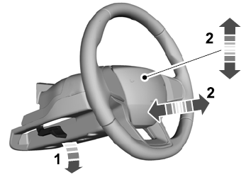
Adjusting the Steering Wheel - Vehicles With: Manual Adjustable Steering Column
WARNING: Do not adjust the steering wheel when your vehicle is moving.
Note: Make sure that you are sitting in the correct position.
Unlock the steering column. Adjust the steering wheel to the desired position.