Lincoln Aviator: Doors and Locks / Locking and Unlocking

Your vehicle has an intelligent electronically controlled door system that is in constant communication with overall vehicle systems.

When you lock your vehicle using the lock switch on each door interior trim panel, or by using the keyless entry keypad or the lock sensor on each door exterior trim panel, the exterior door handle switches do not release the doors. This helps to secure your vehicle and prevent unauthorized entry. Also, when your vehicle reaches a speed greater than 12 mph (20 km/h) the exterior door handle switches do not release the doors.

If the airbags deploy or the fuel pump shutoff switch activates, all interior and exterior unlock switches do not unlock your door for six seconds. This helps to secure the doors in the event of a crash. After six seconds, all switches reset and you can open the doors using the interior and exterior unlatch switches.

Doors and Locks

..

Door Lock Indicator. Door Lock Switch Inhibitor

Door Lock Indicator An LED on each door lock switch illuminates when you lock the doors. It remains on for 2 to 5 seconds after you switch the ignition off...

Other information:

Lincoln Aviator 2020-2023 Service Manual: Diagnosis and Testing - Vehicle Dynamic Suspension - Vehicles With: Air Suspension


Diagnostic Trouble Code (DTC) Chart Diagnostics in this manual assume a certain skill level and knowledge of Ford-specific diagnostic practices. REFER to: Diagnostic Methods (100-00 General Information, Description and Operation).   Diagnostic Trouble Code Chart Module   DTC Description Action   SUMA B1041:52 Levelling Control: Not Activated   GO to Pinpoint Test W   SUMA C1043:00 Pressure Decrease Too Slow From Reservoir: No Sub Type Information   GO to Pinpoint Test M   SUMA C104C:11 Left Rear Spring Rate Valve: Circuit Short To Ground   GO to Pinpoint Test E   SUMA C104C:12 Left Rear Spring Rate Valve: Circuit Short To Battery   GO to Pinpoint Test E   SUMA C104C:13 Left Rear Spring Rate Valve: Circuit Open   GO to Pinpoint Test E   SUMA C104C:1A Left Rear Spring Rate Valve: Circuit Resistance Below Threshold   GO to Pinpoint Test E   SUMA C104C:1F Left Rear Spring Rate Valve: Circuit Intermittent   GO to Pinpoint Test E   SUMA C104D:11 Right Front Spring Rate Valve: Circuit Short To Ground   GO to Pinpoint Test D   SUMA C104D:12 Right Front Spring Rate Valve: Circuit Short To Battery   GO to Pinpoint Test D   SUMA C104D:13 Right Front Spring Rate Valve: Circuit Open   GO to Pinpoint Test D   SUMA C104D:1A Right Front Spring Rate Valve: Circuit Resistance Below Threshold   GO to Pinpoint Test D   SUMA C104D:1F Right Front Spring Rate Valve: Circuit Intermittent   GO to Pinpoint Test D   SUMA C104E:11 Right Rear Spring Rate Valve: Circuit Short To Ground   GO to Pinpoint Test F   SUMA C104E:12 Right Rear Spring Rate Valve: Circuit Short To Battery   GO to Pinpoint Test F   SUMA C104E:13 Right Rear Spring Rate Valve: Circuit Open   GO to Pinpoint Test F   SUMA C104E:1A Right Rear Spring Rate Valve: Circuit Resistance Below Threshold   GO to Pinpoint Test F   SUMA C104E:1F Right Rear Spring Rate Valve: Circuit Intermittent   GO to Pinpoint Test F   SUMA C104F:11 Left Front Spring Rate Valve: Circuit Short To Ground   GO to Pinpoint Test C   SUMA C104F:12 Left Front Spring Rate Valve: Circuit Short To Battery   GO to Pinpoint Test C   SUMA C104F:13 Left Front Spring Rate Valve: Circuit Open   GO to Pinpoint Test C   SUMA C104F:1A Left Front Spring Rate Valve: Circuit Resistance Below Threshold   GO to Pinpoint Test C   SUMA C104F:1F Left Front Spring Rate Valve: Circuit Intermittent   GO to Pinpoint Test C   SUMA C1124:07 Height Sensor(s): Mechanical Failures   GO to Pinpoint Test G   SUMA C1124:11 Height Sensor(s): Circuit Short To Ground   GO to Pinpoint Test H   SUMA C1124:12 Height Sensor(s): Circuit Short To Battery   GO to Pinpoint Test H   SUMA C1124:54 Height Sensor(s): Missing Calibration   GO to Pinpoint Test U   SUMA C1A03:2A Left Front Height Sensor: Stuck in Range   GO to Pinpoint Test I   SUMA C1A03:34 Left Front Height Sensor: Signal High Time Less Than Minimum   GO to Pinpoint Test I   SUMA C1A03:35 Left Front Height Sensor: Signal High Time Greater Than Maximum   GO to Pinpoint Test I   SUMA C1A03:36 Left Front Height Sensor: Signal Frequency Too Low   GO to Pinpoint Test I   SUMA C1A03:37 Left Front Height Sensor: Signal Frequency Too High   GO to Pinpoint Test I   SUMA C1A03:84 Left Front Height Sensor: Signal Below Allowable Range   GO to Pinpoint Test I   SUMA C1A03:85 Left Front Height Sensor: Signal Above Allowable Range   GO to Pinpoint Test I   SUMA C1A04:2A Right Front Height Sensor: Stuck in Range   GO to Pinpoint Test J   SUMA C1A04:34 Right Front Height Sensor: Signal High Time Less Than Minimum   GO to Pinpoint Test J   SUMA C1A04:35 Right Front Height Sensor: Signal High Time Greater Than Maximum   GO to Pinpoint Test J   SUMA C1A04:36 Right Front Height Sensor: Signal Frequency Too Low   GO to Pinpoint Test J   SUMA C1A04:37 Right Front Height Sensor: Signal Frequency Too High   GO to Pinpoint Test J   SUMA C1A04:84 Right Front Height Sensor: Signal Below Allowable Range   GO to Pinpoint Test J   SUMA C1A04:85 Right Front Height Sensor: Signal Above Allowable Range   GO to Pinpoint Test J   SUMA C1A05:2A Left Rear Height Sensor: Stuck in Range   GO to Pinpoint Test K   SUMA C1A05:34 Left Rear Height Sensor: Signal High Time Less Than Minimum   GO to Pinpoint Test K   SUMA C1A05:35 Left Rear Height Sensor: Signal High Time Greater Than Maximum   GO to Pinpoint Test K   SUMA C1A05:36 Left Rear Height Sensor: Signal Frequency Too Low   GO to Pinpoint Test K   SUMA C1A05:37 Left Rear Height Sensor: Signal Frequency Too High   GO to Pinpoint Test K   SUMA C1A05:84 Left Rear Height Sensor: Signal Below Allowable Range   GO to Pinpoint Test K   SUMA C1A05:85 Left Rear Height Sensor: Signal Above Allowable Range   GO to Pinpoint Test K   SUMA C1A06:2A Right Rear Height Sensor: Stuck in Range   GO to Pinpoint Test L   SUMA C1A06:34 Right Rear Height Sensor: Signal High Time Less Than Minimum   GO to Pinpoint Test L   SUMA C1A06:35 Right Rear Height Sensor: Signal High Time Greater Than Maximum   GO to Pinpoint Test L   SUMA C1A06:36 Right Rear Height Sensor: Signal Frequency Too Low   GO to Pinpoint Test L   SUMA C1A06:37 Right Rear Height Sensor: Signal Frequency Too High   GO to Pinpoint Test L   SUMA C1A06:84 Right Rear Height Sensor: Signal Below Allowable Range   GO to Pinpoint Test L   SUMA C1A06:85 Right Rear Height Sensor: Signal Above Allowable Range   GO to Pinpoint Test L   SUMA C1A20:00 Pressure Increase Too Slow When Filling Reservoir: No Sub Type Information   GO to Pinpoint Test M   SUMA C1A27:09 Compressor: Component Failures   GO to Pinpoint Test N   SUMA C1A27:63 Compressor: Circuit/Component Protection Time-Out   GO to Pinpoint Test N   SUMA C1A27:98 Compressor: Component Or System Over Temperature   GO to Pinpoint Test N   SUMA C1A27:99 Compressor: Exceeded Learning Limit   GO to Pinpoint Test N   SUMA C1A31:63 Left Front Corner Valve: Circuit/Component Protection Time-Out   GO to Pinpoint Test AD   SUMA C1A32:63 Right Front Corner Valve: Circuit/Component Protection Time-Out   GO to Pinpoint Test AD   SUMA C1A33:63 Left Rear Corner Valve: Circuit/Component Protection Time-Out   GO to Pinpoint Test AD   SUMA C1A34:63 Right Rear Corner Valve: Circuit/Component Protection Time-Out   GO to Pinpoint Test AD   SUMA C1A36:63 Exhaust Valve: Circuit/Component Protection Time-Out   GO to Pinpoint Test AD   SUMA U0100:87 Lost Communication With ECM / PCM: Missing Message   GO to Pinpoint Test O   SUMA U0121:87 Lost Communication With Anti-Lock Brake System (ABS) Control Module: Missing Message   GO to Pinpoint Test P   SUMA U0122:87 Lost Communication With Vehicle Dynamics Control Module: Missing Message   GO to Pinpoint Test Q   SUMA U0131:87 Lost Communication With Power Steering Control Module "A": Missing Message   GO to Pinpoint Test R   SUMA U0140:87 Lost Communication With Body Control Module: Missing Message   GO to Pinpoint Test S   SUMA U0146:87 Lost Communication With Serial Data Gateway "A": Missing Message   GO to Pinpoint Test T   SUMA U0401:00 Invalid Data Received from ECM/PCM A: No Sub Type Information   GO to Pinpoint Test X   SUMA U0415:00 Invalid Data Received from Anti-Lock Brake System (ABS) Control Module "A": No Sub Type Information   GO to Pinpoint Test Y   SUMA U0416:00 Invalid Data Received From Vehicle Dynamics Control Module: No Sub Type Information   GO to Pinpoint Test Z   SUMA U0420:00 Invalid Data Received from Power Steering Control Module "A": No Sub Type Information   GO to Pinpoint Test AA   SUMA U0422:00 Invalid Data Received From Body Control Module: No Sub Type Information   GO to Pinpoint Test AB   SUMA U0447:00 Invalid Data Received From Serial Data Gateway "A": No Sub Type Information   GO to Pinpoint Test AC   SUMA U2100:00 Initial Configuration Not Complete: No Sub Type Information   GO to Pinpoint Test V   SUMA U2100:56 Initial Configuration Not Complete: Invalid/Incompatible Configuration   GO to Pinpoint Test V   SUMA U3000:04 Control Module: System Internal Failures   GO to Pinpoint Test V   SUMA U3000:45 Control Module: Program Memory Failure   GO to Pinpoint Test V   SUMA U3000:46 Control Module: Calibration/Parameter Memory Failure   GO to Pinpoint Test V   SUMA U3000:47 Control Module: Watchdog/Safety µC Failure   GO to Pinpoint Test V   SUMA U3000:48 Control Module: Supervision Software Failure   GO to Pinpoint Test V   SUMA U3003:16 Battery Voltage: Circuit Voltage Below Threshold   GO to Pinpoint Test A   SUMA U3003:17 Battery Voltage: Circuit Voltage Above Threshold   GO to Pinpoint Test B Symptom Chart Symptom Chart: Vehicle Dynamic Suspension Diagnostics in this manual assume a certain skill level and knowledge of Ford-specific diagnostic practices...

Lincoln Aviator 2020-2023 Service Manual: Removal and Installation - Downshift Paddle Switch


Removal NOTE: Removal steps in this procedure may contain installation details. Remove the steering wheel. Refer to: Steering Wheel (211-04 Steering Column, Removal and Installation). Refer to: Steering Wheel - Vehicles With: Adaptive Steering (211-04 Steering Column, Removal and Installation)...

Categories

Activating Intelligent Access

The intelligent access key must be within 3 ft (1 m) of the door or luggage compartment you intend to lock or unlock.

At a Door

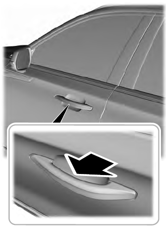
Electronic door handles are on each door. Gently depress the switch inside the exterior door handle to unlock and open the door. An unlock symbol illuminates on the door window trim indicating your vehicle is unlocked.
Lincoln Aviator. Activating Intelligent Access

read more

 
Copyright © 2023 www.liaviator2.com