Lincoln Aviator: Locking and Unlocking / Emergency Locking
Each door has a backup power system which allows the door to function if your vehicle has no power. The system has a limited number of operations before the power is depleted and turns off. When the system turns off, the door remains open and unlatched and does not close.
If your vehicle has no power and the backup power system is turned off, you can close and secure your vehicle by manually resetting each door latch using a key in the position shown.
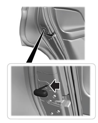
Left-Hand Side
Turn clockwise to reset the latch.
Right-Hand Side
Turn counterclockwise to reset the latch.
When you have reset the latch, you are then able to fully close and latch the door.
Note: You cannot open the door again until the vehicle battery is fully charged and operational.
 Locking the Doors from the Luggage Compartment
Press the lock switch on the liftgate on the
left-hand side. The doors can no longer be
released using the exterior door handle
switches and the luggage compartment
locks...
 Unlatching the Driver Door with the Key Blade
If your vehicle has no power and the backup
power system is turned off, you can manually
unlatch the driver door using a key in the
position shown.
Remove the key blade from the
transmitter...
Other information:
Lincoln Aviator 2020-2026 Owners Manual: Principle of Operation
WARNING: To help avoid personal injury, always use caution when in reverse (R) and when using the sensing system. WARNING: The system may not detect objects with surfaces that absorb reflection. Always drive with due care and attention. Failure to take care may result in a crash...
Lincoln Aviator 2020-2026 Owners Manual: Activating Intelligent Access
The intelligent access key must be within 3 ft (1 m) of the door or luggage compartment you intend to lock or unlock. At a Door Electronic door handles are on each door. Gently depress the switch inside the exterior door handle to unlock and open the door...
Categories
- Manuals Home
- Lincoln Aviator Owners Manual
- Lincoln Aviator Service Manual
- Locking and Unlocking
- Anti-Theft Alarm
- Disabling Auto-Start-Stop
- New on site
- Most important about car
Child Safety Locks
When the child safety locks are set, you cannot open the rear doors from the inside.

The child safety lock control is on the driver door.
Press the control to switch the child safety locks on. Press the control again to switch them off. A light on the child safety control illuminates when you switch them on.