Lincoln Aviator: Locking and Unlocking / Activating Intelligent Access
The intelligent access key must be within 3 ft (1 m) of the door or luggage compartment you intend to lock or unlock.
At a Door
Electronic door handles are on each door. Gently depress the switch inside the exterior door handle to unlock and open the door. An unlock symbol illuminates on the door window trim indicating your vehicle is unlocked.
pro-medicinu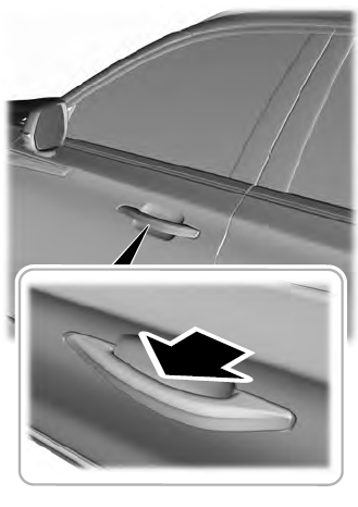
Locking sensors are on both front doors. When the intelligent access key is within 3 ft (1 m) of your vehicle you can lock your vehicle by touching the locking sensor below the keyless entry keypad. Doing so causes a lock symbol to illuminate on the door window trim indicating your vehicle is locked and you can no longer release the door using the exterior door handle switches. Touching the locking sensor when the intelligent access key is not within 3 ft (1 m) causes the lock status to display, but does not lock the doors.
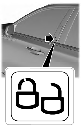
Swipe across the locking sensor to display the current lock status of your vehicle. The lock status also displays when you open a door or when the lock status changes.
Note: You cannot use the locking sensors to unlock your vehicle.
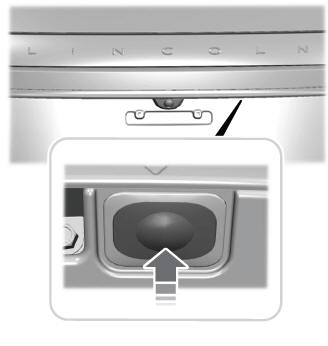
At the Luggage Compartment
Press the exterior release button.
 Door Lock Indicator. Door Lock Switch Inhibitor
Door Lock Indicator
An LED on each door lock switch illuminates
when you lock the doors. It remains on for
2 to 5 seconds after you switch the ignition
off...
 Remote Control
You can use the remote control at any time.
When you press the lock button on the
remote control, all exterior door handle
switches do not release the doors...
Other information:
Lincoln Aviator 2020-2026 Service Manual: Removal and Installation - Roof Front Frame
Special Tool(s) / General Equipment Resistance Spotwelding Equipment Spot Weld Drill Bit Locking Pliers Removal WARNING: Before beginning any service procedure in this manual, refer to health and safety warnings in section 100-00 General Information...
Lincoln Aviator 2020-2026 Owners Manual: Anti-Theft Alarm
The active anti-theft system is designed to warn you in the event of unauthorized vehicle entry and is also designed to help prevent unwanted towing of your vehicle. You can choose what is monitored by arming the system in different ways. The direction indicators flash and the horn sounds if the system triggers while the alarm is armed...
Categories
- Manuals Home
- Lincoln Aviator Owners Manual
- Lincoln Aviator Service Manual
- Changing the Front Wiper Blades - Vehicles With: Heated Wiper Blades
- Configuring The Head Up Display
- Drive Modes
- New on site
- Most important about car
Seatbelt Height Adjustment
WARNING: Position the seatbelt height adjuster so that the seatbelt rests across the middle of your shoulder. Failure to adjust the seatbelt correctly could reduce its effectiveness and increase the risk of injury in a crash.
Adjust the height of the shoulder belt so the belt rests across the middle of your shoulder. Slide the adjuster up to raise the belt. Press the button and slide it down to lower the belt.