Lincoln Aviator: Steering Wheel / Adjusting the Steering Wheel - Vehicles With: Manual Adjustable Steering
Column
WARNING: Do not adjust the steering
wheel when your vehicle is moving.
Note: Make sure that you are sitting in the
correct position.
- Unlock the steering column.
- Adjust the steering wheel to the desired
position.
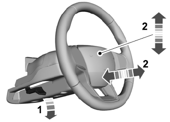
- Lock the steering column.
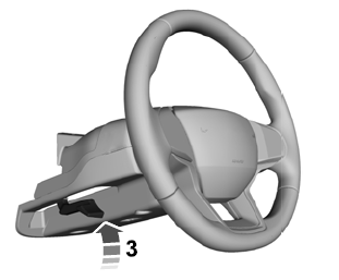
WARNING: Do not adjust the steering
wheel when your vehicle is moving.
Note: Make sure that you are sitting in the
correct position.
Use the control on the side of the steering
column to adjust the position...
Other information:
Steering Column Switches Overview
The
steering column switches are located on and around the steering column.
They enable the driver to control various vehicle functions while
remaining focused on driving. The steering column switches consist of:
Left multifunction switch - mounted on the left side of the SCCM and is used:
to control the turn signals, low/high beam selection
and the flash-to-pass feature (vehicles without police package)...
Diagnostic Trouble Code (DTC) Chart
Diagnostics in this manual assume a certain skill level and knowledge of Ford-specific diagnostic practices. REFER to: Diagnostic Methods (100-00 General Information, Description and Operation).
Diagnostic Trouble Code Chart
Module
DTC
Description
Action
ABS
B1111:4B
Electric Park Brake Enable:Over Temperature
GO to Pinpoint Test F
ABS
B1111:53
Electric Park Brake Enable:Deactivated
GO to Pinpoint Test G
ABS
B1111:54
Electric Park Brake Enable:Missing Calibration
GO to Pinpoint Test E
ABS
C0609:01
Park Brake Switch Circuit:General Electrical Failure
GO to Pinpoint Test B
ABS
C0616:9A
Park Brake Control Module Control Circuit Performance:Component or System Operating Conditions
GO to Pinpoint Test B
ABS
C1034:01
Park Brake:General Electrical Failure
GO to Pinpoint Test B
ABS
C1034:07
Park Brake:Mechanical Failures
GO to Pinpoint Test K
ABS
C1034:13
Park Brake:Circuit Open
GO to Pinpoint Test B
ABS
C1034:25
Park Brake:Signal Shape/Waveform Failure
GO to Pinpoint Test B
ABS
C1034:2F
Park Brake:Signal Erratic
GO to Pinpoint Test B
ABS
C1034:47
Park Brake:Watchdog/Safety µC Failure
GO to Pinpoint Test B
ABS
C1034:48
Park Brake:Supervision Software Failure
GO to Pinpoint Test B
ABS
C1034:57
Park Brake:Invalid/Incompatible Software Component
GO to Pinpoint Test B
ABS
C1034:71
Park Brake:Actuator Stuck
GO to Pinpoint Test C
ABS
C1034:77
Park Brake:Commanded Position Not Reachable
GO to Pinpoint Test C
ABS
C1034:78
Park Brake:Alignment Or Adjustment Incorrect
GO to Pinpoint Test H
ABS
C1034:97
Park Brake:Component or System Operation Obstructed or Blocked
GO to Pinpoint Test D
ABS
C1A43:98
Motor Supply:Component or System Over Temperature
GO to Pinpoint Test D
ABS
C2005:18
Right Actuator:Circuit Current Below Threshold
GO to Pinpoint Test D
ABS
C2005:19
Right Actuator:Circuit Current Above Threshold
GO to Pinpoint Test D
ABS
C2005:77
Right Actuator:Commanded Position Not Reachable
GO to Pinpoint Test C
ABS
C2005:78
Right Actuator:Alignment Or Adjustment Incorrect
GO to Pinpoint Test A
ABS
C2006:18
Left Actuator:Circuit Current Below Threshold
GO to Pinpoint Test D
ABS
C2006:19
Left Actuator:Circuit Current Above Threshold
GO to Pinpoint Test D
ABS
C2006:77
Left Actuator:Commanded Position Not Reachable
GO to Pinpoint Test C
ABS
C2006:78
Left Actuator:Alignment Or Adjustment Incorrect
GO to Pinpoint Test A
ABS
C2007:13
Right Motor:Circuit Open
GO to Pinpoint Test D
ABS
C2007:1C
Right Motor:Circuit Voltage Out Of Range
GO to Pinpoint Test D
ABS
C2007:92
Right Motor:Performance Or Incorrect Operation
GO to Pinpoint Test D
ABS
C2008:13
Left Motor:Circuit Open
GO to Pinpoint Test D
ABS
C2008:1C
Left Motor:Circuit Voltage Out Of Range
GO to Pinpoint Test D
ABS
C2008:92
Left Motor:Performance Or Incorrect Operation
GO to Pinpoint Test D
ABS
U2002:00
Switch:No Sub Type Information
GO to Pinpoint Test J
ABS
U2002:47
Switch:Watchdog/Safety µC Failure
GO to Pinpoint Test B
Symptom Chart(s)
Symptom Chart: Parking Brake and Actuation
Diagnostics in this manual assume a certain skill level and knowledge of Ford-specific diagnostic practices...
Categories
The front outboard and rear safety restraints
in the vehicle are combination lap and
shoulder belts.
Insert the belt tongue into the proper
buckle (the buckle closest to the direction
the tongue is coming from) until you hear
a snap and feel it latch. Make sure that
you securely fasten the tongue in the
buckle.
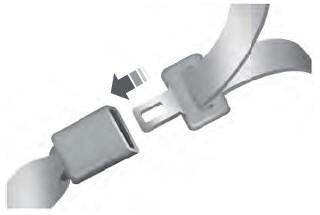
To unfasten, press the release button
and remove the tongue from the buckle.
read more