Lincoln Aviator: Steering Wheel / Adjusting the Steering Wheel - Vehicles With: Power Adjustable Steering Column
WARNING: Do not adjust the steering wheel when your vehicle is moving.
Note: Make sure that you are sitting in the correct position.
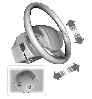
Use the control on the side of the steering column to adjust the position.
To adjust:
- Tilt: Press the top or bottom of the control.
- Telescope: Press the front or rear of the control.
End of Travel Position
The steering column stops just short of the end of the column travel to prevent damage to the steering column. A new stopping position sets if it encounters an object when tilting or telescoping.
To reset the steering column to its normal stopping position:
- Confirm there is nothing obstructing the motion of the steering column.
- Press and hold the steering column control until the steering column stops moving.
- Press the steering column control again.
Note: The steering column may begin to move again.
- When the steering column stops, continue holding the control for a few seconds.
- Repeat for each direction as necessary.
A new stopping position sets. The next time you tilt or telescope the steering column, it stops just short of the end of the column travel.
Memory Feature
You can save and recall the steering column position with the memory function.
Pressing the adjustment control during a memory recall cancels the operation.
Easy Entry and Exit Feature
The column moves up when you switch the ignition off. Switch the ignition on to return the system to its previous settings. You can switch this feature on or off through the touchscreen.
Note: If you press any adjustment or memory button when in easy exit mode, the system cancels the operation.
Note: Depending on your vehicle, the column may move up and in.
 Adjusting the Steering Wheel - Vehicles With: Manual Adjustable Steering
Column
Adjusting the Steering Wheel - Vehicles With: Manual Adjustable Steering
Column
WARNING: Do not adjust the steering
wheel when your vehicle is moving.
Note: Make sure that you are sitting in the
correct position.
Unlock the steering column...
 Audio and Voice Control
Audio Control
You can operate the following
functions with the control:
Move the selector switch up to
increase volume level.
Move the selector switch down to
decrease volume level...
Other information:
Lincoln Aviator 2020-2026 Service Manual: Removal and Installation - Heater Core
Removal NOTE: If a heater core leak is suspected, the heater core must be leak tested before it is removed from the vehicle. Remove the climate control housing. Refer to: Climate Control Housing (412-00 Climate Control System - General Information, Removal and Installation)...
Lincoln Aviator 2020-2026 Service Manual: Diagnosis and Testing - Parking Aid
Diagnostic Trouble Code (DTC) Chart Diagnostics in this manual assume a certain skill level and knowledge of Ford-specific diagnostic practices. REFER to: Diagnostic Methods (100-00 General Information, Description and Operation). Diagnostic Trouble Code Chart Module DTC Description Action APIM C1001:01 Vision System Camera:General Electrical Failure GO to Pinpoint Test A APIM C1001:01 Vision System Camera:General Electrical Failure GO to Pinpoint Test J APIM C1001:02 Vision System Camera:General Signal Failure GO to Pinpoint Test A APIM C1001:1C Vision System Camera:Circuit Voltage Out Of Range GO to Pinpoint Test A APIM C1001:4B Vision System Camera:Over Temperature GO to Pinpoint Test H APIM C1001:55 Vision System Camera:Not Configured GO to Pinpoint Test I APIM C1001:81 Vision System Camera:Invalid Serial Data Received GO to Pinpoint Test A APIM C1001:87 Vision System Camera:Missing Message GO to Pinpoint Test A IPMB B115E:31 Camera Module:No Signal GO to Pinpoint Test L IPMB B115E:49 Camera Module:Internal Electronic Failure GO to Pinpoint Test T IPMB B12BE:31 Left Front Camera:No Signal GO to Pinpoint Test N IPMB B12BE:49 Left Front Camera:Internal Electronic Failure GO to Pinpoint Test U IPMB B12BF:31 Right Front Camera:No Signal GO to Pinpoint Test O IPMB B12BF:49 Right Front Camera:Internal Electronic Failure GO to Pinpoint Test V IPMB B148E:31 Front Camera:No Signal GO to Pinpoint Test M IPMB B148E:49 Front Camera:Internal Electronic Failure GO to Pinpoint Test W IPMB B14A5:11 Multi-Camera View Switch:Circuit Short To Ground GO to Pinpoint Test P IPMB C1001:78 Vision System Camera:Alignment Or Adjustment Incorrect GO to Pinpoint Test X IPMB U0100:00 Lost Communication With ECM/PCM "A":No Sub Type Information GO to Pinpoint Test Y IPMB U0121:00 Lost Communication With Anti-Lock Brake System (ABS) Control Module:No Sub Type Information GO to Pinpoint Test Z IPMB U0121:87 Lost Communication With Anti-Lock Brake System (ABS) Control Module "A":Missing Message GO to Pinpoint Test Z IPMB U0131:00 Lost Communication With Power Steering Control Module:No Sub-Type Information GO to Pinpoint Test AA IPMB U0131:87 Lost Communication With Power Steering Control Module "A":Missing Message GO to Pinpoint Test AA IPMB U0138:00 Lost Communication with All Terrain Control Module:No Sub Type Information GO to Pinpoint Test AB IPMB U0140:00 Lost Communication With Body Control Module:No Sub Type Information GO to Pinpoint Test AC IPMB U0146:00 Lost Communication With Gateway "A":No Sub Type Information GO to Pinpoint Test AD IPMB U0212:00 Lost Communication With Steering Column Control Module:No Sub Type Information GO to Pinpoint Test AJ IPMB U0253:87 Lost Communication With Accessory Protocol Interface Module:Missing Message GO to Pinpoint Test AK IPMB U0293:00 Lost Communication with Hybrid/EV Powertrain Control Module:No Sub Type Information GO to Pinpoint Test Y IPMB U0300:57 Internal Control Module Software Incompatibility:Invalid/Incompatible Software Component GO to Pinpoint Test AN IPMB U0401:00 Invalid Data Received from ECM/PCM A:No Sub Type Information GO to Pinpoint Test Y IPMB U0415:00 Invalid Data Received from Anti-Lock Brake System (ABS) Control Module "A":No Sub Type Information GO to Pinpoint Test Z IPMB U0420:00 Invalid Data Received from Power Steering Control Module "A":No Sub Type Information GO to Pinpoint Test AA IPMB U0422:00 Invalid Data Received From Body Control Module:No Sub Type Information GO to Pinpoint Test AC IPMB U0423:82 Invalid Data Received from Instrument Panel Cluster Control Module:Alive/Sequence Counter Incorrect/Not Updated GO to Pinpoint Test AE IPMB U0424:00 Invalid Data Received From HVAC Control Module:No Sub Type Information GO to Pinpoint Test AF IPMB U0424:82 Invalid Data Received From HVAC Control Module:Alive/Sequence Counter Incorrect/Not Updated GO to Pinpoint Test AF IPMB U0428:00 Invalid Data Received From Steering Angle Sensor Module:No Sub Type Information GO to Pinpoint Test AG IPMB U0485:82 Invalid Data Received From Radio:Alive/Sequence Counter Incorrect/Not Updated GO to Pinpoint Test AH IPMB U0553:82 Invalid Data Received From Lighting Control Module-Rear "B":Alive/Sequence Counter Incorrect/Not Updated GO to Pinpoint Test AI IPMB U0554:00 Invalid Data Received From Accessory Protocol Interface Module:No Sub Type Information GO to Pinpoint Test AK IPMB U0554:82 Invalid Data Received From Accessory Protocol Interface Module:Alive/Sequence Counter Incorrect/Not Updated GO to Pinpoint Test AK IPMB U0594:00 Invalid Data Received From Hybrid/EV Powertrain Control Module:No Sub Type Information GO to Pinpoint Test Y IPMB U1000:11 Solid State Driver Protection Active -Driver Disabled:Circuit Short To Ground GO to Pinpoint Test AL IPMB U2024:41 Control Module Cal-Config Data:General Checksum Failure GO to Pinpoint Test AM IPMB U2100:00 Initial Configuration Not Complete:No Sub Type Information GO to Pinpoint Test AM IPMB U2101:00 Control Module Configuration Incompatible:No Sub Type Information GO to Pinpoint Test AM IPMB U3000:42 Control Module:General Memory Failure GO to Pinpoint Test AN IPMB U3000:49 Control Module:Internal Electronic Failure GO to Pinpoint Test AN Symptom Chart(s) Rear Only Parking Aid Camera Diagnostics in this manual assume a certain skill level and knowledge of Ford-specific diagnostic practices...
Categories
- Manuals Home
- Lincoln Aviator Owners Manual
- Lincoln Aviator Service Manual
- Description and Operation - Body and Frame
- Child Safety Locks
- Fuel Quality
- New on site
- Most important about car
Activating Intelligent Access
The intelligent access key must be within 3 ft (1 m) of the door or luggage compartment you intend to lock or unlock.
At a Door
Electronic door handles are on each door. Gently depress the switch inside the exterior door handle to unlock and open the door. An unlock symbol illuminates on the door window trim indicating your vehicle is unlocked.
