Lincoln Aviator: Steering Wheel / Audio and Voice Control
Audio Control
You can operate the following functions with the control:
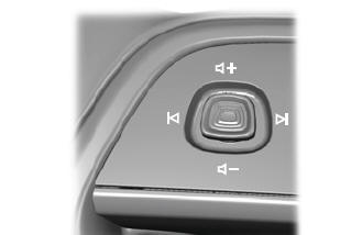
 Move the selector switch up to
increase volume level.
Move the selector switch up to
increase volume level.
 Move the selector switch down to
decrease volume level.
Move the selector switch down to
decrease volume level.
 Move the selector switch to the
left
to access the previous media
selection.
Move the selector switch to the
left
to access the previous media
selection.
 Move the selector switch to the
right to access the next media
selection.
Move the selector switch to the
right to access the next media
selection.
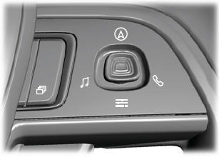
Note: The controls change when you enter a submenu.
The following controls are not available when you enter a submenu:
 Move the selector switch to the
right to enter the mode phone
submenu.
Move the selector switch to the
right to enter the mode phone
submenu.
 Move the selector switch to the
left
to enter the media submenu.
Move the selector switch to the
left
to enter the media submenu.
Voice Control
The controls are on the steering wheel.
 Press
and release to activate voice
recognition.
Press
and release to activate voice
recognition.
 Adjusting the Steering Wheel - Vehicles With: Power Adjustable Steering
Column
Adjusting the Steering Wheel - Vehicles With: Power Adjustable Steering
Column
WARNING: Do not adjust the steering
wheel when your vehicle is moving.
Note: Make sure that you are sitting in the
correct position.
Use the control on the side of the steering
column to adjust the position...

Other information:
Lincoln Aviator 2020-2026 Owners Manual: Principle of Operation
WARNING: Airbags do not inflate slowly or gently, and the risk of injury from a deploying airbag is the greatest close to the trim covering the airbag module. WARNING: All occupants of your vehicle, including the driver, should always properly wear their seatbelts, even when an airbag supplemental restraint system is provided...
Lincoln Aviator 2020-2026 Owners Manual: Updating the System
Updating the System Using a USB Drive Downloading an Update Go to the SYNC update page on the regional website. Download the update.Note: The website notifies you if an update is available. Insert a USB drive into your computer.Note: The USB drive needs to be empty and meet the minimum requirements detailed on the website...
Categories
- Manuals Home
- Lincoln Aviator Owners Manual
- Lincoln Aviator Service Manual
- Body and Paint
- Drive Modes
- Keyless Entry
- New on site
- Most important about car
Adjusting the Steering Wheel - Vehicles With: Manual Adjustable Steering Column
WARNING: Do not adjust the steering wheel when your vehicle is moving.
Note: Make sure that you are sitting in the correct position.
Unlock the steering column. Adjust the steering wheel to the desired position.