Lincoln Aviator: Parking Aids / Front Parking Aid
WARNING: The system may not detect objects with surfaces that absorb reflection. Always drive with due care and attention. Failure to take care may result in a crash.
WARNING: The system may not detect small or moving objects, particularly those close to the ground.
WARNING: To help avoid personal injury, always use caution when in reverse (R) and when using the sensing system.
WARNING: The parking aid system can only assist you to detect objects when your vehicle is moving at parking speeds. To help avoid personal injury you must take care when using the parking aid system.
Note: Keep the sensors free from snow, ice and large accumulations of dirt.
Note: Do not cover up the sensors.
Note: Do not clean the sensors with sharp objects.
Note: If your vehicle sustains damage leaving the sensors misaligned, this may cause inaccurate measurements or false alerts.
Note: Some accessories, for example large trailer hitches or bike or surfboard racks can cause reduced performance or false alerts.
The sensors are on the front bumper.
The sensors are active when the transmission is in any position other than park (P). When the parking aid system sounds a tone, the audio system may reduce the set volume.
A warning tone sounds when your vehicle approaches an object. As your vehicle moves closer to an object, the rate of the tone increases. The warning tone continuously sounds when an object is 12 in (30 cm) or less from the front bumper.
Note: There is a decreased coverage area at the outer corners.
The system turns off when the vehicle speed reaches 5 mph (8 km/h).
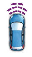
The sensor coverage area is up to 28 in (70 cm) from the center of the bumper.
If the transmission is in reverse (R), the system detects objects when your vehicle is moving at low speed or an object is moving toward your vehicle, for example another vehicle at low speed. When you stop your vehicle, the audible warning turns off after two seconds.
If the transmission is in any forward gear, the system provides audible warnings when your vehicle is moving and an object is within the detection area. When you stop your vehicle, the audible warning turns off after two seconds and the visual warning turns off after four seconds.
If the system detects a fault, a warning message appears in the information display.
Object Distance Indicator (If Equipped)
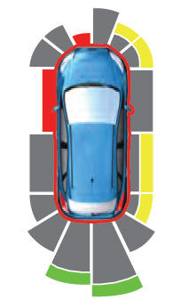
The system provides object distance indication through the information display.
- As the distance to the object decreases, the indicator blocks illuminate and move toward the vehicle icon.
- If there is no object detected, the distance indicator blocks are gray.
When you shift into any forward gear, the system provides audible warnings and visual indication when your vehicle is moving at a speed of approximately 5 mph (8 km/h) or below and the system detects an object within the detection zone. When you stop your vehicle, the audible warnings stop after two seconds and visual indication stops after four seconds.
Note: If the detected object is 12 in (30 cm) or less from your vehicle, visual indication remains on.
When you shift into neutral (N), the system only provides visual indication if your vehicle is moving at a speed of approximately 5 mph (8 km/h) or below, for example, your vehicle is moving on a slope, and the system detects an object moving toward your vehicle. When you stop your vehicle, visual indication stops after four seconds.
 Rear Parking Aid
WARNING: The system may not
detect objects with surfaces that absorb
reflection. Always drive with due care and
attention. Failure to take care may result
in a crash...
 Side Sensing System
WARNING: The system may not
detect objects with surfaces that absorb
reflection. Always drive with due care and
attention. Failure to take care may result
in a crash...
Other information:
Lincoln Aviator 2020-2026 Owners Manual: Utilizing the Mediation/Arbitration Program (Canada Only)
For vehicles delivered to authorized Canadian dealers. In those cases where you continue to feel that the efforts by Ford of Canada and the authorized dealer to resolve a factory-related vehicle service concern have been unsatisfactory, Ford of Canada participates in an impartial third party mediation/arbitration program administered by the Canadian Motor Vehicle Arbitration Plan (CAMVAP)...
Lincoln Aviator 2020-2026 Owners Manual: 30-Way Seat Controls
The power seat controls are on the door. Head restraint. Lumbar support. Memory function. Independent leg and thigh seat extensions. Seat adjust (forward, backward, height and tilt). Upper seat backrest. Recline. Press this button to access the lumbar menu on the touchscreen...
Categories
- Manuals Home
- Lincoln Aviator Owners Manual
- Lincoln Aviator Service Manual
- USB Port and Power Point Locations
- Wireless Accessory Charger (If Equipped)
- Description and Operation - Body and Frame
- New on site
- Most important about car
Activating Intelligent Access
The intelligent access key must be within 3 ft (1 m) of the door or luggage compartment you intend to lock or unlock.
At a Door
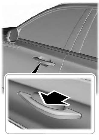
Electronic door handles are on each door. Gently depress the switch inside the exterior door handle to unlock and open the door. An unlock symbol illuminates on the door window trim indicating your vehicle is unlocked.