Lincoln Aviator: Entertainment / HD Radio™ Information (If Available)
To activate HD radio, please see the Radio
Settings in the Settings Chapter.
Note: HD Radio broadcasts are not available
in all markets.
HD Radio technology is the digital evolution
of analog AM/FM radio. Your system has a
special receiver that allows it to receive
digital broadcasts (where available) in
addition to the analog broadcasts, it already
receives. Digital broadcasts provide a better
sound quality than analog broadcasts with
free, crystal-clear audio and no static or
distortion. For more information, and a guide
to available stations and programming,
please visit:
Website
www.hdradio.com
When HD Radio is on and you tune to a
station broadcasting HD Radio technology,
you may notice the following indicators on
your screen:
The HD logo is grey when acquiring a digital
station, and then changes to orange when
digital audio is playing. When this logo is
available, you may also see Title and Artist
fields on-screen.
The multicast indicator appears in FM mode
(only) if the current station is broadcasting
multiple digital broadcasts. The highlighted
numbers signify available digital channels
where new or different content is available.
HD1 signifies the main programming status
and is available in analog and digital
broadcasts. Other multicast stations (HD2
through HD7) are only available digitally.
Note: There is also an additional feature for
stations that have more than 1 HD multicast
(For example, HD1 or HD2). The HD logo and
Radio text appears as a button. Pressing this
button allows you to cycle through all of the
HD stations on that specific frequency. For
example, if you are on 101.1 and it has HD1,
HD2, HD3, pressing the button repeatedly
causes the radio to cycle through the HD
stations in a cyclic increasing order.
When HD Radio broadcasts are active, you can access the following
functions:
Note: As with any station you save, you cannot access the saved station
if your vehicle is outside the station’s reception area.
HD Radio Reception and Station Troubleshooting
In order to provide the best possible
experience, use the contact form to report
any station issues found while listening to a
station broadcasting with HD Radio
technology. Independent entities own and
operate each station. These stations are
responsible for ensuring all audio streams
and data fields are accurate.
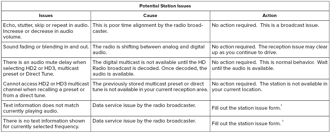
1 You can find the form here:
Website
http://hdradio.com/stations/feedback
HD Radio Technology manufactured under
license from iBiquity Digital Corporation and
foreign patents. HD Radio and the HD and
HD Radio logos are proprietary trademarks
of DTS. The vehicle manufacturer and DTS
are not responsible for the content sent using
HD Radio technology. Content may be
changed, added or deleted at any time at
the station owner's discretion.
Note: This feature may not be available in
all markets and requires an active
subscription.
SiriusXM satellite radio is a
subscription-based satellite radio service that
broadcasts a variety of music, sports, news,
weather, traffic and entertainment
programming...
Once you select this option, the system
returns you to the main audio screen.
The current audio information appears on
the screen.
The following buttons are also available:
You can use the forward, reverse, pause or
play buttons to control the audio playback...
Other information:
Removal
Remove the air cleaner intake pipe.
Refer to: Air Cleaner Intake Pipe (303-12 Intake Air Distribution and Filtering - 3.0L EcoBoost/3.0L EcoBoost – Hybrid (BQ), Removal and Installation).
Remove the CAC outlet pipe.
Refer to: Charge Air Cooler (CAC) Outlet Pipe (303-12 Intake Air Distribution and Filtering - 3...
Diagnostic Trouble Code (DTC) Chart
Diagnostics in this manual assume a certain skill level and knowledge of Ford-specific diagnostic practices. REFER to: Diagnostic Methods (100-00 General Information, Description and Operation).
Diagnostic Trouble Code Chart
Module
DTC
Description
Action
IPMB
B1303:13
Park Assist Switch:Circuit Open
GO to Pinpoint Test D
IPMB
B1303:9E
Park Assist Switch:Stuck On
GO to Pinpoint Test D
IPMB
B1B36:08
Right Front Outer Sensor:Bus Signal/Message Failure
GO to Pinpoint Test I
IPMB
B1B36:96
Right Front Outer Sensor: Component Internal Failure
GO to Pinpoint Test N
IPMB
B1B36:98
Right Front Outer Sensor:Component Or System Over Temperature
GO to Pinpoint Test O
IPMB
B1B38:08
Right Front Inner Sensor:Bus Signal/Message Failure
GO to Pinpoint Test J
IPMB
B1B38:96
Right Front Inner Sensor: Component Internal Failure
GO to Pinpoint Test N
IPMB
B1B38:98
Right Front Inner Sensor:Component Or System Over Temperature
GO to Pinpoint Test O
IPMB
B1B40:08
Left Front Outer Sensor:Bus Signal/Message Failure
GO to Pinpoint Test K
IPMB
B1B40:96
Left Front Outer Sensor: Component Internal Failure
GO to Pinpoint Test N
IPMB
B1B40:98
Left Front Outer Sensor:Component Or System Over Temperature
GO to Pinpoint Test O
IPMB
B1B42:08
Left Front Inner Sensor:Bus Signal/Message Failure
GO to Pinpoint Test L
IPMB
B1B42:96
Left Front Inner Sensor: Component Internal Failure
GO to Pinpoint Test N
IPMB
B1B42:98
Left Front Inner Sensor:Component Or System Over Temperature
GO to Pinpoint Test O
IPMB
B1B44:08
Right Rear Outer Sensor:Bus Signal/Message Failure
GO to Pinpoint Test E
IPMB
B1B44:96
Right Rear Outer Sensor: Component Internal Failure
GO to Pinpoint Test M
IPMB
B1B44:98
Right Rear Outer Sensor:Component Or System Over Temperature
GO to Pinpoint Test P
IPMB
B1B46:08
Right Rear Inner Sensor:Bus Signal/Message Failure
GO to Pinpoint Test F
IPMB
B1B46:96
Right Rear Inner Sensor: Component Internal Failure
GO to Pinpoint Test M
IPMB
B1B46:98
Right Rear Inner Sensor:Component Or System Over Temperature
GO to Pinpoint Test P
IPMB
B1B48:08
Left Rear Outer Sensor:Bus Signal/Message Failure
GO to Pinpoint Test G
IPMB
B1B48:96
Left Rear Outer Sensor: Component Internal Failure
GO to Pinpoint Test M
IPMB
B1B48:98
Left Rear Outer Sensor:Component Or System Over Temperature
GO to Pinpoint Test P
IPMB
B1B50:08
Left Rear Inner Sensor:Bus Signal/Message Failure
GO to Pinpoint Test H
IPMB
B1B50:96
Left Rear Inner Sensor: Component Internal Failure
GO to Pinpoint Test M
IPMB
B1B50:98
Left Rear Inner Sensor:Component Or System Over Temperature
GO to Pinpoint Test P
IPMB
B1B57:11
Front Sensors Power Circuit: Circuit Short To Ground
GO to Pinpoint Test B
IPMB
B1B58:11
Rear Sensors Power Circuit: Circuit Short To Ground
GO to Pinpoint Test C
IPMB
U0428:00
Invalid Data Received From Steering Angle Sensor Module:No Sub Type Information
GO to Pinpoint Test Z
PAM
B1303:13
Park Assist Switch:Circuit Open
GO to Pinpoint Test D
PAM
B1303:9E
Park Assist Switch:Stuck On
GO to Pinpoint Test D
PAM
B1B36:08
Right Front Outer Sensor:Bus Signal/Message Failure
GO to Pinpoint Test I
PAM
B1B36:1F
Right Front Outer Sensor:Circuit Intermittent
GO to Pinpoint Test I
PAM
B1B36:31
Right Front Outer Sensor:No Signal
GO to Pinpoint Test I
PAM
B1B36:96
Right Front Outer Sensor: Component Internal Failure
GO to Pinpoint Test N
PAM
B1B36:98
Right Front Outer Sensor:Component Or System Over Temperature
GO to Pinpoint Test O
PAM
B1B38:08
Right Front Inner Sensor:Bus Signal/Message Failure
GO to Pinpoint Test J
PAM
B1B38:1F
Right Front Inner Sensor:Circuit Intermittent
GO to Pinpoint Test J
PAM
B1B38:31
Right Front Inner Sensor:No Signal
GO to Pinpoint Test J
PAM
B1B38:96
Right Front Inner Sensor: Component Internal Failure
GO to Pinpoint Test N
PAM
B1B38:98
Right Front Inner Sensor:Component Or System Over Temperature
GO to Pinpoint Test O
PAM
B1B40:08
Left Front Outer Sensor:Bus Signal/Message Failure
GO to Pinpoint Test K
PAM
B1B40:1F
Left Front Outer Sensor:Circuit Intermittent
GO to Pinpoint Test K
PAM
B1B40:31
Left Front Outer Sensor:No Signal
GO to Pinpoint Test K
PAM
B1B40:96
Left Front Outer Sensor: Component Internal Failure
GO to Pinpoint Test N
PAM
B1B40:98
Left Front Outer Sensor:Component Or System Over Temperature
GO to Pinpoint Test O
PAM
B1B42:08
Left Front Inner Sensor:Bus Signal/Message Failure
GO to Pinpoint Test L
PAM
B1B42:1F
Left Front Inner Sensor:Circuit Intermittent
GO to Pinpoint Test L
PAM
B1B42:31
Left Front Inner Sensor:No Signal
GO to Pinpoint Test L
PAM
B1B42:96
Left Front Inner Sensor: Component Internal Failure
GO to Pinpoint Test N
PAM
B1B42:98
Left Front Inner Sensor:Component Or System Over Temperature
GO to Pinpoint Test O
PAM
B1B44:08
Right Rear Outer Sensor:Bus Signal/Message Failure
GO to Pinpoint Test E
PAM
B1B44:1F
Right Rear Outer Sensor:Circuit Intermittent
GO to Pinpoint Test E
PAM
B1B44:31
Right Rear Outer Sensor:No Signal
GO to Pinpoint Test E
PAM
B1B44:96
Right Rear Outer Sensor: Component Internal Failure
GO to Pinpoint Test M
PAM
B1B44:98
Right Rear Outer Sensor:Component Or System Over Temperature
GO to Pinpoint Test P
PAM
B1B46:08
Right Rear Inner Sensor:Bus Signal/Message Failure
GO to Pinpoint Test F
PAM
B1B46:1F
Right Rear Inner Sensor:Circuit Intermittent
GO to Pinpoint Test F
PAM
B1B46:31
Right Rear Inner Sensor:No Signal
GO to Pinpoint Test F
PAM
B1B46:96
Right Rear Inner Sensor: Component Internal Failure
GO to Pinpoint Test M
PAM
B1B46:98
Right Rear Inner Sensor:Component Or System Over Temperature
GO to Pinpoint Test P
PAM
B1B48:08
Left Rear Outer Sensor:Bus Signal/Message Failure
GO to Pinpoint Test G
PAM
B1B48:1F
Left Rear Outer Sensor:Circuit Intermittent
GO to Pinpoint Test G
PAM
B1B48:31
Left Rear Outer Sensor:No Signal
GO to Pinpoint Test G
PAM
B1B48:96
Left Rear Outer Sensor: Component Internal Failure
GO to Pinpoint Test M
PAM
B1B48:98
Left Rear Outer Sensor:Component Or System Over Temperature
GO to Pinpoint Test P
PAM
B1B50:08
Left Rear Inner Sensor:Bus Signal/Message Failure
GO to Pinpoint Test H
PAM
B1B50:1F
Left Rear Inner Sensor:Circuit Intermittent
GO to Pinpoint Test H
PAM
B1B50:31
Left Rear Inner Sensor:No Signal
GO to Pinpoint Test H
PAM
B1B50:96
Left Rear Inner Sensor: Component Internal Failure
GO to Pinpoint Test M
PAM
B1B50:98
Left Rear Inner Sensor:Component Or System Over Temperature
GO to Pinpoint Test P
PAM
B1B57:11
Front Sensors Power Circuit: Circuit Short To Ground
GO to Pinpoint Test B
PAM
B1B58:11
Rear Sensors Power Circuit: Circuit Short To Ground
GO to Pinpoint Test C
PAM
U0100:00
Lost Communication With ECM/PCM "A": No Sub Type Information
GO to Pinpoint Test R
PAM
U0121:00
Lost Communication With Anti-Lock Brake System (ABS) Control Module: No Sub Type Information
GO to Pinpoint Test S
PAM
U0131:00
Lost Communication With Power Steering Control Module: No Sub-Type Information
GO to Pinpoint Test T
PAM
U0138:00
Lost Communication with All Terrain Control Module:No Sub Type Information
GO to Pinpoint Test U
PAM
U0140:00
Lost Communication With Body Control Module: No Sub Type Information
GO to Pinpoint Test V
PAM
U0146:00
Lost Communication With Gateway "A": No Sub Type Information
GO to Pinpoint Test W
PAM
U0155:00
Lost Communication With Instrument Panel Cluster (IPC) Control Module: No Sub Type Information
GO to Pinpoint Test X
PAM
U0164:00
Lost Communication With HVAC Control Module: No Sub Type Information
GO to Pinpoint Test Y
PAM
U0212:00
Lost Communication With Steering Column Control Module: No Sub Type Information
GO to Pinpoint Test AB
PAM
U0252:00
Lost Communication With Lighting Control Module- Rear "B": No Sub Type Information
GO to Pinpoint Test AC
PAM
U0293:00
Lost Communication with Hybrid/EV Powertrain Control Module:No Sub Type Information
GO to Pinpoint Test R
PAM
U0300:57
Internal Control Module Software Incompatibility:Invalid/Incompatible Software Component
GO to Pinpoint Test AG
PAM
U0401:00
Invalid Data Received from ECM/PCM A:No Sub Type Information
GO to Pinpoint Test R
PAM
U0415:00
Invalid Data Received from Anti-Lock Brake System (ABS) Control Module "A":No Sub Type Information
GO to Pinpoint Test S
PAM
U0420:00
Invalid Data Received from Power Steering Control Module "A":No Sub Type Information
GO to Pinpoint Test T
PAM
U0422:00
Invalid Data Received From Body Control Module:No Sub Type Information
GO to Pinpoint Test V
PAM
U0423:82
Invalid Data Received from Instrument Panel
Cluster Control Module:Alive/Sequence Counter Incorrect/Not Updated
GO to Pinpoint Test X
PAM
U0424:00
Invalid Data Received From HVAC Control Module:No Sub Type Information
GO to Pinpoint Test Y
PAM
U0424:82
Invalid Data Received From HVAC Control Module:Alive/Sequence Counter Incorrect/Not Updated
GO to Pinpoint Test Y
PAM
U0485:82
Invalid Data Received From Radio:Alive/Sequence Counter Incorrect/Not Updated
GO to Pinpoint Test AA
PAM
U0553:82
Invalid Data Received From Lighting Control
Module-Rear "B":Alive/Sequence Counter Incorrect/Not Updated
GO to Pinpoint Test AC
PAM
U0554:00
Invalid Data Received From Accessory Protocol Interface Module:No Sub Type Information
GO to Pinpoint Test AD
PAM
U0554:82
Invalid Data Received From Accessory
Protocol Interface Module:Alive/Sequence Counter Incorrect/Not Updated
GO to Pinpoint Test AD
PAM
U0594:00
Invalid Data Received From Hybrid/EV Powertrain Control Module:No Sub Type Information
GO to Pinpoint Test R
PAM
U1000:00
Solid State Driver Protection Active -Driver Disabled:No Sub Type Information
GO to Pinpoint Test AE
PAM
U2024:41
Control Module Cal-Config Data:General Checksum Failure
GO to Pinpoint Test AF
PAM
U2100:00
Initial Configuration Not Complete:No Sub Type Information
GO to Pinpoint Test AF
PAM
U2101:00
Control Module Configuration Incompatible:No Sub Type Information
GO to Pinpoint Test AF
PAM
U3000:44
Control Module:Data Memory Failure
GO to Pinpoint Test AG
PAM
U3000:45
Control Module:Program Memory Failure
GO to Pinpoint Test AG
PAM
U3000:46
Control Module:Calibration/Parameter Memory Failure
GO to Pinpoint Test AG
PAM
U3000:49
Control Module:Internal Electronic Failure
GO to Pinpoint Test AG
Symptom Chart(s)
Symptom Chart: Parking Aid
Condition
Possible Sources
Actions
A module does not communicate with the diagnostic scan tool
Fuse
Wiring, terminals or connectors
PAM
IPMB
REFER to: Communications Network (418-00 Module Communications Network, Diagnosis and Testing)...