Lincoln Aviator: Installing Child Restraints / Child Seats
Use a child restraint (sometimes called an infant carrier, convertible seat, or toddler seat) for infants, toddlers and children weighing 40 lb (18 kg) or less (generally four-years-old or younger).
Using Lap and Shoulder Belts
WARNING: Do not place a rearward facing child restraint in front of an active airbag. Failure to follow this instruction could result in personal injury or death.
WARNING: Properly secure children 12 years old and under in a rear seating position whenever possible. If you are unable to properly secure all children in a rear seating position, properly secure the largest child on the front seat. If you must use a forward facing child restraint on the front seat, move the seat as far back as possible. Failure to follow these instructions could result in personal injury or death.
WARNING: Depending on where you secure a child restraint, and depending on the child restraint design, you may block access to certain seatbelt buckle assemblies and LATCH lower anchors, rendering those features potentially unusable. To avoid risk of injury, make sure occupants only use seating positions where they are able to be properly restrained.
When installing a child restraint with combination lap and shoulder belts:
- Use the correct seatbelt buckle for that seating position.
- Insert the belt tongue into the proper buckle until you hear a snap and feel it latch. Make sure the tongue is securely fastened in the buckle.
- Keep the buckle release button pointing up and away from the child restraint, with the tongue between the child restraint and the release button, to prevent accidental unbuckling.
- Place the vehicle seat in the upright position before you install the child restraint.
- For second row seating positions, adjust the recliner slightly to improve child restraint fit. If needed, remove the head restraints.
- For third row seating positions, stow the head restraints to improve child restraint fit.
- Put the seatbelt in the automatic locking mode. See Step 5. This vehicle does not require the use of a locking clip.
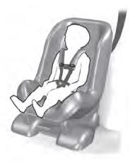
Perform the following steps when installing the child restraint with combination lap and shoulder belts:
Note: Although the child restraint illustrated is a forward facing child restraint, the steps are the same for installing a rear facing child restraint.
Note: Follow all instructions provided by the manufacturer of the child restraint regarding the necessary and proper use of the lock-off device. In some instances these devices have been provided only for use in vehicles with seatbelt systems that would otherwise require a locking clip.
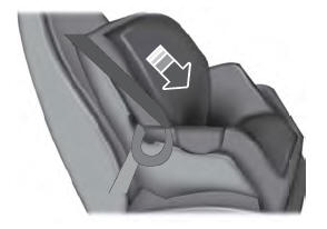
- Position the child restraint in a seat with
a combination lap and shoulder belt.
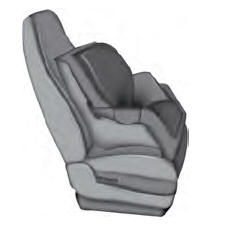
- After positioning the child restraint in the
proper seating position, pull down on the
shoulder belt and then grasp the
shoulder belt and lap belt together
behind the belt tongue.
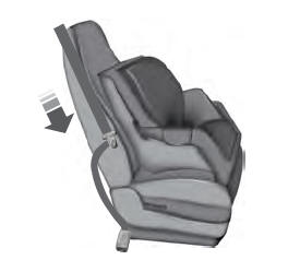
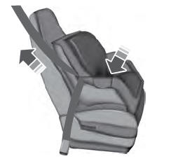
- While holding the shoulder and lap belt
portions together, route the tongue
through the child restraint according to
the child restraint manufacturer's
instructions. Make sure you do not twist
the belt webbing.
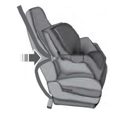
- Insert the belt tongue into the proper
buckle (the buckle closest to the direction
the tongue is coming from) for that
seating position until you hear a snap and
feel the latch engage. Make sure you
securely latch the tongue by pulling on
it.
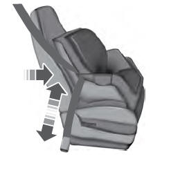
- To put the retractor in the automatic
locking mode, grasp the shoulder portion
of the belt and pull downward until you
pull all of the belt out.
Note: The automatic locking mode is available on the front passenger and rear seats.
- Allow the belt to retract to remove slack. The belt clicks as it retracts to indicate it is in the automatic locking mode.
- Try to pull the belt out of the retractor to
make sure the retractor is in the
automatic locking mode. You should not
be able to pull more belt out. If the
retractor did not lock, unbuckle the belt
and repeat Steps 5 and 6.
- Remove remaining slack from the belt.
Force the seat down with extra weight,
for example, by pressing down or
kneeling on the child restraint as you pull
up on the shoulder belt to force slack
from the belt. This is necessary to remove
the remaining slack that exists once you
add the extra weight of the child to the
child restraint. It also helps to achieve the
proper snugness of the child restraint to
your vehicle. Sometimes, a slight lean
toward the buckle provides extra help to
remove remaining slack from the belt.
- If the child restraint has a tether strap, attach it.
- Before placing the child in the seat,
forcibly move the seat forward and back
to make sure you have the seat
securely held in place. To check this,
grab the seat at the belt path and
attempt to move it side to side and
forward and back. There should be no
more than 1 in (2.5 cm) of movement for
proper installation.
We recommend checking with a NHTSA Certified Child Passenger Safety Technician to make certain the child restraint is properly installed. In Canada, check with Transport Canada for referral to a Child Car Seat Clinic.

 Using Lower Anchors and Tethers for CHildren (LATCH)
WARNING: Do not attach two child
safety restraints to the same anchor. In a
crash, one anchor may not be strong
enough to hold two child safety restraint
attachments and may break, causing
serious injury or death...
Other information:
Lincoln Aviator 2020-2026 Owners Manual: Notice to utility vehicle and truck owners
WARNING: Vehicles with a higher center of gravity (utility and four-wheel drive vehicles) handle differently than vehicles with a lower center of gravity (passenger cars). Avoid sharp turns, excessive speed and abrupt steering in these vehicles...
Lincoln Aviator 2020-2026 Owners Manual: Changing the Engine Air Filter
WARNING: To reduce the risk of vehicle damage and personal burn injuries, do not start your engine with the air cleaner removed and do not remove it while the engine is running. When changing the engine air filter, do not allow debris or foreign material to enter the air induction system...
Categories
- Manuals Home
- Lincoln Aviator Owners Manual
- Lincoln Aviator Service Manual
- Child Safety Locks
- Wireless Accessory Charger (If Equipped)
- Fuel Quality
- New on site
- Most important about car
Emergency Locking
Each door has a backup power system which allows the door to function if your vehicle has no power. The system has a limited number of operations before the power is depleted and turns off. When the system turns off, the door remains open and unlatched and does not close.
If your vehicle has no power and the backup power system is turned off, you can close and secure your vehicle by manually resetting each door latch using a key in the position shown.