Lincoln Aviator 2020-2025 Service Manual / Electrical / Climate Control System / Supplemental Climate Control / Removal and Installation - High Voltage Battery Coolant Cooler
Lincoln Aviator: Supplemental Climate Control / Removal and Installation - High Voltage Battery Coolant Cooler
Special Tool(s) / General Equipment
| Hose Clamp(s) | |
| Hose Clamp Remover/Installer |
Removal
NOTICE: During the removal of components, cap, tape or otherwise appropriately protect all openings to prevent the ingress of dirt or other contamination. Remove protective materials prior to installation.
NOTE: Removal steps in this procedure may contain installation details.
-
Recover the refrigerant. Refer to the appropriate Recovery procedure in Group 412.
-
Remove the engine rear undershield.
Refer to: Engine Rear Undershield (501-02 Front End Body Panels, Removal and Installation).
-
-
Disconnect the electrical connector.
-
Remove the retainer and position aside the manifold assembly
Torque: 159 lb.in (18 Nm)
-
Remove the mounting retainers.
Torque: 80 lb.in (9 Nm)
-
Make sure to cover any open ports to prevent debris from entering the system.
-
Disconnect the electrical connector.
.jpg) |
-
Remove the bolts and the suspension support bar.
Torque: 22 lb.ft (30 Nm)
.jpg) |
- Remove the LH CAC intake pipe. Refer to the appropriate procedure in Group 303.
-
Remove the A/C compressor outlet line mounting bracket retainer and position aside the line.
Torque: 80 lb.in (9 Nm)
.jpg) |
-
Disconnect the coolant hose and remove the high voltage battery coolant cooler.
Use the General Equipment: Hose Clamp(s)
Use the General Equipment: Hose Clamp Remover/Installer
.jpg) |
Installation
-
To install, reverse the removal procedure.
-
NOTICE: Only use the specified material to lubricate the seals.
Install and lubricate new O-ring seals. Refer to the appropriate Specifications in Group 412.
-
Lubricate the refrigerant system with the correct amount
of clean POE oil. Refer to the appropriate Refrigerant Oil Adding
procedure in Group 412.
-
Fill the electric powertrain cooling system.
Refer to: Engine Cooling System Draining, Vacuum Filling and Bleeding (303-03A Engine Cooling - 3.0L EcoBoost, General Procedures).
 Removal and Installation - Cabin Heater Coolant Temperature Sensor
Removal
NOTE:
Removal steps in this procedure may contain installation details.
Drain the cooling system.
Refer to: Engine Cooling System Draining, Vacuum Filling and Bleeding (303-03A Engine Cooling - 3...
 Removal and Installation - Rear Evaporator Shutoff Valve
Removal
NOTE:
The rear evaporator shutoff valve is available only as part of the rear evaporator.
Remove the rear evaporator.
Refer to: Rear Evaporator (412-02A Rear Climate Control, Removal and Installation)...
Other information:
Lincoln Aviator 2020-2025 Service Manual: General Procedures - Brake Disc Machining
Repair NOTE: On-Vehicle Brake Lathe Training Videos Vehicle preparation. Click here to view a video version of this procedure. Mounting the machine. Click here to view a video version of this procedure...
Lincoln Aviator 2020-2025 Service Manual: Disassembly and Assembly - Wheel and Tire
Special Tool(s) / General Equipment Wooden Block DISASSEMBLY NOTICE: Failure to follow the instructions below may result in damage to the TPMS. NOTICE: The TPMS sensor is mounted to the valve stem. Removal of the valve stem requires dismounting the tire from the wheel and removal of the TPMS sensor...
Categories
- Manuals Home
- Lincoln Aviator Owners Manual
- Lincoln Aviator Service Manual
- Locking and Unlocking
- Interior Lamps
- Changing the Front Wiper Blades - Vehicles With: Heated Wiper Blades
- New on site
- Most important about car
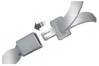
Fastening the Seatbelts
The front outboard and rear safety restraints in the vehicle are combination lap and shoulder belts.
Insert the belt tongue into the proper buckle (the buckle closest to the direction the tongue is coming from) until you hear a snap and feel it latch. Make sure that you securely fasten the tongue in the buckle.
Copyright © 2025 www.liaviator2.com
