Lincoln Aviator 2020-2024 Service Manual / Electrical / Electronic Feature Group / Lane Keeping System / Removal and Installation - Image Processing Module A (IPMA)

Lincoln Aviator: Lane Keeping System / Removal and Installation - Image Processing Module A (IPMA)

Removal

  1. Release the clips and remove the IPMA cover.
  1. Disconnect the electrical connector.
  1. Release the tabs and remove the IPMA.

Installation


  1. Install the IPMA.
    1. Install the lower tabs.
    1. Install the upper tabs.
  1. To install, reverse the removal procedure.

    • If a new IPMA has been installed, using a diagnostic scan tool, complete the PMI process for the IPMA following the on-screen instructions.
    • If a new IPMA has been installed, carry out the camera alignment using a scan tool.

    Diagnosis and Testing - Lane Keeping System

    DTC Chart(s) Diagnostics in this manual assume a certain skill level and knowledge of Ford-specific diagnostic practices. REFER to: Diagnostic Methods (100-00 General Information, Description and Operation)...

    Multifunction Electronic Modules

    ..

    Other information:

    Lincoln Aviator 2020-2024 Service Manual: Removal and Installation - B-Pillar Trim Panel


    Special Tool(s) / General Equipment Interior Trim Remover Removal NOTE: LH (left hand) shown, RH (right hand) similar. Upper and lower B-pillar trim panels Remove the following items: Remove the front scuff plate trim panel...

    Lincoln Aviator 2020-2024 Service Manual: Diagnosis and Testing - Steering Wheel and Column Electrical Components


    Diagnostic Trouble Code (DTC) Chart Diagnostics in this manual assume a certain skill level and knowledge of Ford-specific diagnostic practices. REFER to: Diagnostic Methods (100-00 General Information, Description and Operation).   Diagnostic Trouble Code Chart Module   DTC Description Action   BCM B108A:01 Start Button: General Electrical Failure   GO to Pinpoint Test A   BCM B108A:24 Start Button: Signal Stuck High   GO to Pinpoint Test A   BCM B1142:29 Ignition Status 1: Signal Invalid   GO to Pinpoint Test A   BCM B1240:11 Start Button Mode Indicator: Circuit Short to Ground   GO to Pinpoint Test B   BCM B1240:15 Start Button Mode Indicator: Circuit Short to Battery or Open   GO to Pinpoint Test C   BCM B1310:12 Run/Start Control: Circuit Short to Battery   GO to Pinpoint Test A   BCM B1310:14 Run/Start Control: Circuit Short to Ground or Open   GO to Pinpoint Test A   SCCM B112B:04 SCCM:Steering Wheel Module: System Internal Failure   GO to Pinpoint Test I   SCCM B112B:44 SCCM:Steering Wheel Module: Data Memory Failure   GO to Pinpoint Test I   SCCM B112B:45 SCCM:Steering Wheel Module: Program Memory Failure   GO to Pinpoint Test I   SCCM B112B:46 SCCM:Steering Wheel Module: Calibration / Parameter Memory Failure   GO to Pinpoint Test I   SCCM B112B:49 SCCM:Steering Wheel Module: Internal Electronic Failure   GO to Pinpoint Test I   SCCM B135C:11 Heater Element:Circuit Short To Ground   GO to Pinpoint Test G   SCCM B135C:13 Heater Element:Circuit Open   GO to Pinpoint Test G   SCCM U0140:00 Lost Communication With Body Control Module: No Sub Type Information   GO to Pinpoint Test H   SCCM U0140:00 SCCM:Lost Communication With Body Control Module: No Sub Type Information   GO to Pinpoint Test J   SCCM U0146:00 SCCM:Lost Communication With Gateway "A": No Sub Type Information   GO to Pinpoint Test J   SCCM U0146:87 SCCM:Lost Communication With Gateway "A": No Sub Type Information   GO to Pinpoint Test J   SCCM U0155:00 SCCM:Lost Communication With Instrument Panel Cluster Module: No Sub Type Information   GO to Pinpoint Test J   SCCM U023A:00 SCCM:Lost Communication With Image Processing Module "A": No Sub Type Information   GO to Pinpoint Test J   SCCM U0241:00 SCCM:Lost Communication With Headlamp Control Module: No Sub Type Information   GO to Pinpoint Test J   SCCM U210A:11 Temperature Sensor:Circuit Short To Ground   GO to Pinpoint Test G   SCCM U210A:13 Temperature Sensor:Circuit Open   GO to Pinpoint Test G   SCCM U3003:A2 Battery Voltage: System Voltage Low   GO to Pinpoint Test E   SCCM U3003:A3 Battery Voltage:System Voltage High   GO to Pinpoint Test F   SECM B135C:11 Heater Element:Circuit Short To Ground   GO to Pinpoint Test K   SECM B135C:15 Heater Element:Circuit Short to Battery or Open   GO to Pinpoint Test K   SECM B13BD:92 Steering Wheel Heater Module:Performance or Incorrect Operation   GO to Pinpoint Test K   SECM U1000:00 Solid State Driver Protection Active:No Sub Type Information   GO to Pinpoint Test K   SECM U210A:02 Temperature Sensor:General Signal Failure   GO to Pinpoint Test K   SECM U210A:11 Temperature Sensor:Circuit Short to Ground   GO to Pinpoint Test K   SECM U210A:15 Temperature Sensor:Circuit Short to Battery or Open   GO to Pinpoint Test K   SIMA U0100:00 Lost Communication With ECM/PCM "A": No Sub Type Information   GO to Pinpoint Test L   SIMA U0140:00 Lost Communication With Body Control Module: No Sub Type Information   GO to Pinpoint Test L   SIMA U3003:16 Battery Voltage:Battery Voltage Below Threshold   GO to Pinpoint Test M   SIMA U3003:17 Battery Voltage:Battery Voltage Above Threshold   GO to Pinpoint Test N Symptom Charts Symptom Chart: Ignition Switch - Push Button Diagnostics in this manual assume a certain skill level and knowledge of Ford-specific diagnostic practices...

    Categories

    Child Safety Locks

    When the child safety locks are set, you cannot open the rear doors from the inside.
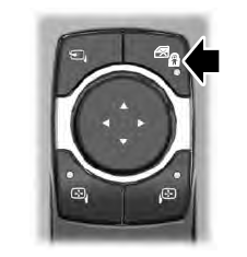
    Lincoln Aviator. Child Safety Locks

    The child safety lock control is on the driver door.

    Press the control to switch the child safety locks on. Press the control again to switch them off. A light on the child safety control illuminates when you switch them on.

    read more

     
    Copyright © 2024 www.liaviator2.com