Lincoln Aviator: Changing the 12V Battery / Battery Management System (If Equipped)
The battery management system monitors battery conditions and takes actions to extend battery life. If excessive battery drain is detected, the system temporarily disables some electrical systems to protect the battery.
Systems included are:
- Heated rear window.
- Heated seats.
- Climate control.
- Heated steering wheel.
- Audio unit.
- Navigation system.
A message may appear in the information displays to alert you that battery protection actions are active. These messages are only for notification that an action is taking place, and not intended to indicate an electrical problem or that the battery requires replacement.
After battery replacement, or in some cases after charging the battery with an external charger, the battery management system requires eight hours of vehicle sleep time to relearn the battery state of charge. During this time your vehicle must remain fully locked with the ignition switched off.
Note: Prior to relearning the battery state of charge, the battery management system may temporarily disable some electrical systems.
Electrical Accessory Installation
To make sure the battery management system works correctly, do not connect an electrical device ground connection directly to the battery negative post. This can cause inaccurate measurements of the battery condition and potential incorrect system operation.
Note: If you add electrical accessories or components to the vehicle, it may adversely affect battery performance and durability. This may also affect the performance of other electrical systems in the vehicle.
 Changing the 12V Battery
WARNING: Batteries normally
produce explosive gases which can cause
personal injury. Therefore, do not allow
flames, sparks or lighted substances to
come near the battery...
 Remove and Reinstall the Battery
To disconnect or remove the battery, do the
following:
Apply the parking brake and switch the
ignition off.
Switch all electrical equipment off, for
example lights and radio...
Other information:
Lincoln Aviator 2020-2026 Service Manual: Description and Operation - Module Configuration - System Operation and Component Description
System Operation Programmable Module Installation (PMI) PMI is a diagnostic scan tool process which configures settings in a new module. Data used for the PMI process is automatically downloaded from the original module and stored when a diagnostic scan tool session is started...
Lincoln Aviator 2020-2026 Owners Manual: Starting a Hybrid Electric Vehicle System
Before starting your vehicle, check the following: Make sure all occupants fasten their seatbelt. Make sure the headlamps and electrical accessories are off. Make sure the parking brake is on. Put the transmission in park (P). Note: Do not touch the accelerator pedal...
Categories
- Manuals Home
- Lincoln Aviator Owners Manual
- Lincoln Aviator Service Manual
- Description and Operation - Body and Frame
- Locking and Unlocking
- Changing the Front Wiper Blades - Vehicles With: Heated Wiper Blades
- New on site
- Most important about car
Fastening the Seatbelts
The front outboard and rear safety restraints in the vehicle are combination lap and shoulder belts.
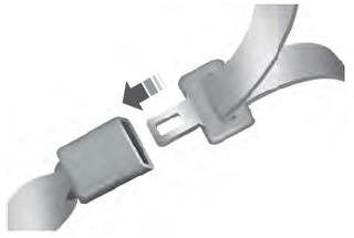
Insert the belt tongue into the proper buckle (the buckle closest to the direction the tongue is coming from) until you hear a snap and feel it latch. Make sure that you securely fasten the tongue in the buckle.
