Lincoln Aviator 2020-2026 Owners Manual / Customer Assistance / Changing a Fuse
Lincoln Aviator: Customer Assistance / Changing a Fuse
Fuses
WARNING: Always replace a fuse with one that has the specified amperage rating. Using a fuse with a higher amperage rating can cause severe wire damage and could start a fire.
If electrical components in the vehicle are not working, a fuse may have blown. Blown fuses are identified by a broken wire within the fuse. Check the appropriate fuses before replacing any electrical components.
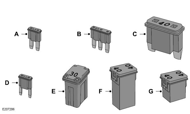
Fuse Types

 Passenger Compartment Fuse Panel
The fuse panel is under the instrument panel
to the left of the steering column.
Note: It may be easier to access the fuse
panel if you remove the finish trim piece...
 Maintenance
..
Other information:
Lincoln Aviator 2020-2026 Service Manual: Removal and Installation - Front Door Tweeter Speaker
Removal NOTE: Removal steps in this procedure may contain installation details. Remove the front door trim panel. Refer to: Front Door Trim Panel (501-05 Interior Trim and Ornamentation, Removal and Installation). Remove the screws and the front door tweeter speaker...
Lincoln Aviator 2020-2026 Service Manual: General Procedures - Rear Toe Adjustment
Special Tool(s) / General Equipment Wheel Alignment System Adjustment NOTICE: Do not use any tools or equipment to move the wheel and tire assembly or suspension components while checking for relative movement. Suspension damage may occur...
Categories
- Manuals Home
- Lincoln Aviator Owners Manual
- Lincoln Aviator Service Manual
- Description and Operation - Body and Frame
- Description and Operation - Jacking and Lifting
- Wireless Accessory Charger (If Equipped)
- New on site
- Most important about car
Adjusting the Steering Wheel - Vehicles With: Manual Adjustable Steering Column
WARNING: Do not adjust the steering wheel when your vehicle is moving.
Note: Make sure that you are sitting in the correct position.
Unlock the steering column. Adjust the steering wheel to the desired position.
Copyright © 2026 www.liaviator2.com