Lincoln Aviator: Fuel and Refueling / Refueling
WARNING: When refueling always shut the engine off and never allow sparks or open flames near the fuel tank filler valve. Never smoke or use a cell phone while refueling. Fuel vapor is extremely hazardous under certain conditions. Avoid inhaling excess fumes.
WARNING: The fuel system may be under pressure. If you hear a hissing sound near the fuel filler inlet, do not refuel until the sound stops. Otherwise, fuel may spray out, which could cause serious personal injury.
WARNING: Do not pry open the fuel tank filler valve. This could damage the fuel system. Failure to follow this instruction could result in fire, personal injury or death.
WARNING: Do not remove the fuel pump nozzle from its fully inserted position when refueling.
WARNING: Stop refueling when the fuel pump nozzle automatically shuts off for the first time. Failure to follow this will fill the expansion space in the fuel tank and could lead to fuel overflowing.
WARNING: Do not overfill the fuel tank. The pressure in an overfilled tank may cause leakage and lead to fuel spray and fire.
WARNING: Wait at least five seconds before removing the fuel pump nozzle to allow any residual fuel to drain into the fuel tank.
WARNING: Read and follow all the instructions on the pump island.
- When you stop your vehicle, shift into
park (P) and switch the ignition off.
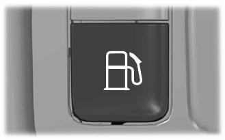
- Press the button on the left side of the
instrument panel next to the headlamp
switch to open the fuel filler door. The
fuel filler door can take up to 15 seconds
to open before you can insert a fuel filler
nozzle.
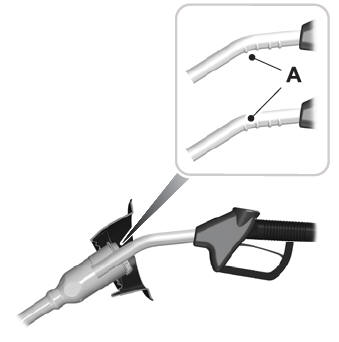
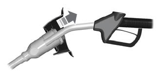
- Insert the fuel pump nozzle up to the first
notch on the nozzle A. Keep it resting
on the cover of the fuel tank filler pipe
opening.
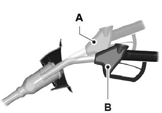
- Hold the fuel pump nozzle in position B
when refueling. Holding the fuel pump
nozzle in position A can affect the flow
of fuel and shut off the fuel pump nozzle
before the fuel tank is full.
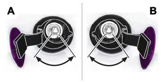
- Operate the fuel pump nozzle within the
area shown.
- When the pump shuts off, wait 5 seconds, then slowly lift and remove the nozzle.
- Fully close the fuel filler door.
Note: To close the fuel filler door, press the center rear edge of the fuel filler door and then release.
Complete the refueling process within 20 minutes. If 20 minutes elapses, press the button on the left side of the instrument panel again. Fuel pump nozzle automatic shut off could occur if you do not press the button on the left side instrument panel.
System Warnings
If the fuel filler door fails to open, an information message appears in the information display.
If the information message appears, do the following:
- Check the fuel filler door for anything that may be obstructing its movement, for example ice or snow.
- Remove any obstruction from the fuel filler door.
- Press the button on the driver door to open the fuel filler door.
- If the fuel filler door fails to open and the information message remains in the information display, use the fuel filler door manual override lever.
Fuel Filler Door Manual Override Lever
WARNING: The fuel system may be under pressure. If you hear a hissing sound near the fuel filler inlet, do not refuel until the sound stops. Otherwise, fuel may spray out, which could cause serious personal injury.
Note: The transmission must be in park (P) or neutral (N).
When using the manual override lever do the following:
- Switch the ignition on.
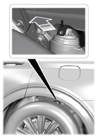
Note: The manual override lever is in the driver side rear wheel well area.
- Pull the manual override lever.
- Switch the ignition off.
- Complete the refueling process within 20 minutes.
 Adding Fuel From a Portable Fuel Container
WARNING: Do not insert the nozzle
of a fuel container or an aftermarket funnel
into the fuel filler neck. This may damage
the fuel system filler neck or its seal and
cause fuel to run onto the ground...
 Fuel Consumption
Advertised Capacity
The advertised capacity is the maximum
amount of fuel that you can add to the fuel
tank when the fuel gauge indicates empty.
In addition, the fuel tank contains an empty
reserve...
Other information:
Lincoln Aviator 2020-2026 Owners Manual: Auto Hold
WARNING: The system does not replace the parking brake. When you leave your vehicle, always apply the parking brake. WARNING: You must remain in your vehicle when the system turns on. At all times, you are responsible for controlling your vehicle, supervising the system and intervening, if required...
Lincoln Aviator 2020-2026 Service Manual: General Procedures - Bezel Diagnostics
Check NOTE: If there is a concern with one of the following components and Bezel Diagnostics cannot be accessed, obtain the module part number by referencing the label attached to the module. Inoperative ACM Inoperative (blank or does not power on) display unit (non-touchscreen display or touchscreen display) Inoperative FCIM or radio control panel Inoperative steering wheel switch Refer to appropriate 415-00 section to diagnose the inoperative component...
Categories
- Manuals Home
- Lincoln Aviator Owners Manual
- Lincoln Aviator Service Manual
- Locking and Unlocking
- Drive Modes
- Tire Change Procedure
- New on site
- Most important about car
Fastening the Seatbelts
The front outboard and rear safety restraints in the vehicle are combination lap and shoulder belts.
Insert the belt tongue into the proper buckle (the buckle closest to the direction the tongue is coming from) until you hear a snap and feel it latch. Make sure that you securely fasten the tongue in the buckle.