Lincoln Aviator: Garage Door Opener
HomeLink Wireless Control System
WARNING: Do not use the system with any garage door opener that does not have the safety stop and reverse feature as required by U.S. Federal Safety Standards (this includes any garage door opener manufactured before April 1, 1982). A garage door opener which cannot detect an object, signaling the door to stop and reverse, does not meet current federal safety standards. Using a garage door opener without these features increases the risk of serious injury or death.
Note: Make sure that the garage door and security device are free from obstruction when you are programming. Do not program the system with the vehicle in the garage.
Note: Make sure you keep the original remote control transmitter for use in other vehicles as well as for future system programming.
Note: We recommend that upon the sale or lease termination of your vehicle, you erase the programmed function buttons for security reasons.
Note: You can program a maximum of three devices. To change or replace any of the three devices after it has been initially programmed, you must first erase the current settings.
The universal garage door opener replaces the common hand-held garage door opener with a three-button transmitter that is integrated into the driver’s sun visor.
The system includes two primary features, a garage door opener and a platform for remote activation of devices within the home. As well as being programmed for garage doors, the system transmitter can be programmed to operate entry gate operators, security systems, entry door locks and home or office lighting.
Additional system information can be found online at www.homelink.com, www.youtube.com/HomeLinkGentex or by calling the toll-free help line on 1-800-355-3515.
In-Vehicle Programming
This process is to program your hand-held transmitter and your in-vehicle HomeLink button.
Note: The programming steps below assume you will be programming HomeLink that was not previously programmed.
Note: Put a new battery in the hand-held transmitter. This will ensure quicker training and accurate transmission of the radio-frequency signal.
- With your vehicle parked outside of the garage, turn your ignition to the on position, but do not start your vehicle.
- Hold your hand-held garage door transmitter 2–6 in (5–14 cm) away from the HomeLink button you want to program.
- Using both hands, simultaneously, press
and hold the desired HomeLink button
and the hand-held transmitter button. DO
NOT release either one until the
HomeLink indicator light flashes slowly
and then rapidly. When the indicator light
flashes rapidly, both buttons may be
released. The rapid flashing indicates
successful training.
Note: You may need to use a different method if you live in Canada or have difficulties programming your gate operator or garage door opener.
- Press and hold the HomeLink button you programmed for two seconds, then release. You may need to do this twice to activate the door. If your garage door does not operate, watch the HomeLink indicator light.
If the indicator light stays on, the programming is complete. No further action is needed.
If the indicator light flashes rapidly for 2 seconds and then turns to a constant light, the HomeLink button is not programmed yet.
To program additional buttons, repeat Steps 1 – 4.
For questions or comments, please contact HomeLink at www.homelink.com, www.youtube.com/HomeLinkGentex or 1-800-355-3515.
Programming Your Garage Door Opener Motor
Note: You may need a ladder to reach the unit and you may need to remove the cover or lamp lens on your garage door opener.
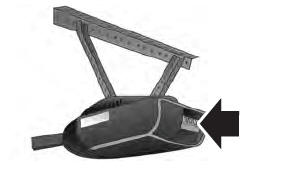
- Press the learn button on the garage door opener motor and then you have 30 seconds to complete the next two steps.
- Return to your vehicle.
- Press and hold the function button you want to program for 2 seconds, then release. Repeat this step. Depending on your brand of garage door opener, you may need to repeat this sequence a third time.
Gate Operator / Canadian Programming
Canadian radio-frequency laws require transmitter signals to “time-out” (or quit) after several seconds of transmission – which may not be long enough for HomeLink to pick up the signal during programming. Similar to this Canadian law, some U.S. gate operators are designed to “time-out” in the same manner.
Note: If programming a garage door opener or gate operator, it is advised to unplug the device during the “cycling” process to prevent possible overheating.
- Press and hold the HomeLink button while you press and release, every two seconds, your hand-held transmitter until the HomeLink indicator light changes from a slow to a rapidly blinking light.
- Release both the HomeLink and hand-held transmitter buttons.
- Continue programing HomeLink.
Erasing the Function Button Codes
Note: You cannot erase individual buttons.
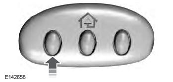
- Press and hold the outer two function buttons simultaneously for approximately 20 seconds until the indicator lights above the buttons flash rapidly.
- When the indicator lights flash, release the buttons. The codes for all buttons are erased.
Reprogramming a Single Button
To program a device to a previously trained button, follow these steps:
- Press and hold the desired button. Do NOT release the button.
- The indicator light will begin to flash after 20 seconds. Without releasing the button, follow Step 1 in the Programming section.
For questions or comments, contact HomeLink at www.homelink.com, www.youtube.com/HomeLinkGentex or 1-800-355-3515.
Programming to a Genie Intellicode 2 Garage Door Opener
Note: The Genie Intellicode 2 transmitter must already be programmed to operate with the garage door opener.
Note: To program HomeLink to the transmitter you must first put the transmitter into programming mode.
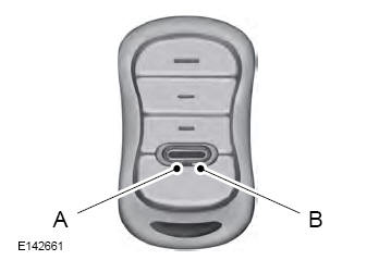
- Red indicator light
- Green indicator light
- Press and hold one of the buttons on the hand-held transmitter for 10 seconds. The indicator light will change from green to red and green.
- Press the same button twice to confirm the change to programming mode. If done properly the indicator light will appear red.
- Hold the transmitter within 1–3 in (2–8 cm) of the button on the visor you want to program.
- Press and hold both the programmed Genie button on the hand-held transmitter and the button you want to program. The indicator light on the visor will flash rapidly when the programming is successful.
Note: The Genie transmitter will transmit for up to 30 seconds. If HomeLink does not program within 30 seconds the Genie transmitter will need to be pressed again. If the Genie transmitter indicator light displays green and red, release the button until the indicator light turns off before pressing the button again.
Once HomeLink has been programmed successfully, the Genie transmitter must be changed out of program mode. To do this:
- Press and hold the previously programmed Genie button on the hand-held transmitter for 10 seconds. The indicator light will change from red to red and green.
- Press the same button twice to confirm the change. If done correctly the indicator light will turn green.
Programming HomeLink to the Genie Intellicode Garage Door Opener Motor
Note: You may need a ladder to access the garage door opener motor.
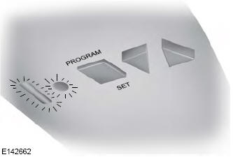
- Press and hold the program button on the garage door opener motor until both blue indicator lights turn on.
- Release the program button. Only the smaller round indicator light should be on.
- Press and release the program button.
The larger purple indicator light will flash.
Note: The next two steps must be completed in 30 seconds.
- Press and release the Genie Intellicode 2 hand-held transmitter’s previously programmed button. Both indicator lights on the garage door opener motor unit should now flash purple.
- Press and hold the previously programmed button on the visor for 2 seconds. Repeat this step up to 3 times until the garage door moves.
Programming is now complete.
Clearing a HomeLink Device
To erase programming from the three HomeLink buttons press and hold the two outer HomeLink buttons until the indicator light begins to flash. The indicator light will begin flashing in 10 to 20 seconds, at which time both buttons should be released. Programming has now been erased, and the indicator light should blink slowly to indicate the device is in train mode when any of the three HomeLink buttons are pressed.
FCC and RSS-210 Industry Canada Compliance
This device complies with Part 15 of the FCC Rules and with RSS-210 of Industry Canada. Operation is subject to the following two conditions: (1) this device may not cause harmful interference, and (2) this device must accept any interference received, including interference that may cause undesired operation.
WARNING: Changes or modifications not expressively approved by the party responsible for compliance could void the user's authority to operate the equipment. The term "IC:" before the radio certification number only signifies that Industry Canada technical specifications were met.
This equipment complies with FCC radiation exposure limits set forth for an uncontrolled environment. End Users must follow the specific operating instructions for satisfying RF exposure compliance. This transmitter must be at least 8 in (20 cm) from the user and must not be co-located or operating in conjunction with any other antenna or transmitter.
The term “IC:” before the certification/registration number only signifies that Industry Canada technical specifications were met.
 Rear Occupant Alert System Indicators and Audible Warnings
Indicators
Message
Check rear seats for occupants.
Displays when you switch your vehicle off
after the alert conditions are met.
The message displays for a short period of
time...

Other information:
Lincoln Aviator 2020-2026 Owners Manual: Notice to utility vehicle and truck owners
WARNING: Vehicles with a higher center of gravity (utility and four-wheel drive vehicles) handle differently than vehicles with a lower center of gravity (passenger cars). Avoid sharp turns, excessive speed and abrupt steering in these vehicles...
Lincoln Aviator 2020-2026 Service Manual: Removal and Installation - High Voltage Battery Coolant Cooler
Special Tool(s) / General Equipment Hose Clamp(s) Hose Clamp Remover/Installer Removal NOTICE: During the removal of components, cap, tape or otherwise appropriately protect all openings to prevent the ingress of dirt or other contamination...
Categories
- Manuals Home
- Lincoln Aviator Owners Manual
- Lincoln Aviator Service Manual
- Configuring The Head Up Display
- Changing the Front Wiper Blades - Vehicles With: Heated Wiper Blades
- Garage Door Opener
- New on site
- Most important about car
Child Safety Locks
When the child safety locks are set, you cannot open the rear doors from the inside.

The child safety lock control is on the driver door.
Press the control to switch the child safety locks on. Press the control again to switch them off. A light on the child safety control illuminates when you switch them on.