Lincoln Aviator 2020-2026 Service Manual / Electrical / Battery and Charging System / Voltage Converter/Inverter / Description and Operation - Direct Current/Alternating Current (DC/AC) Inverter - Overview
Lincoln Aviator: Voltage Converter/Inverter / Description and Operation - Direct Current/Alternating Current (DC/AC) Inverter - Overview
Overview
The DC- AC inverter converts 12 volts DC to 110 volts AC to power a device that uses AC with a power requirement of less than 150 watts.
 Description and Operation - Direct Current/Alternating Current (DC/AC) Inverter - System Operation and Component Description
System Diagram
System Operation
Network Message Chart
Broadcast Message
Originating Module
Message Purpose
Power pack torque status
Secondary On-Board Diagnostic Control Module C (SOBDMC)
Used to determine if the vehicle is started or if torque is available...
Other information:
Lincoln Aviator 2020-2026 Service Manual: Removal and Installation - High Voltage Battery Junction Box - Plug-In Hybrid Electric Vehicle (PHEV)
Removal WARNING: To prevent the risk of high-voltage shock, always follow precisely all warnings and service instructions, including instructions to depower the system. The high-voltage system utilizes approximately 450 volts DC, provided through high-voltage cables to its components and modules...
Lincoln Aviator 2020-2026 Service Manual: Removal and Installation - Steering Column
Removal NOTICE: To prevent damage to the clockspring, make sure the front wheels are in the straight-ahead position. NOTICE: Precise tolerances are required when manufacturing a steering column. Never install a repaired, rebuilt, aftermarket, or remanufactured steering column...
Categories
- Manuals Home
- Lincoln Aviator Owners Manual
- Lincoln Aviator Service Manual
- Keyless Entry
- Locking and Unlocking
- Description and Operation - Jacking and Lifting
- New on site
- Most important about car
Fastening the Seatbelts
The front outboard and rear safety restraints in the vehicle are combination lap and shoulder belts.
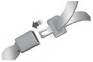
Insert the belt tongue into the proper buckle (the buckle closest to the direction the tongue is coming from) until you hear a snap and feel it latch. Make sure that you securely fasten the tongue in the buckle.
Copyright © 2026 www.liaviator2.com

