Lincoln Aviator 2020-2026 Service Manual / Chassis / Suspension / Tire Pressure Monitoring System (TPMS) / Description and Operation - Tire Pressure Monitoring System (TPMS) - Overview
Lincoln Aviator: Tire Pressure Monitoring System (TPMS) / Description and Operation - Tire Pressure Monitoring System (TPMS) - Overview
Overview
The BCM uses tire pressure sensors to monitor tire pressure. The sensors use radio signals to transmit the tire pressure to the RTM. The RTM sends the information to the BCM over a LIN.
The tire pressure sensors are battery operated and mounted to the valve stems.
The IPC illuminates the TPMS warning indicator and the message center displays a message when a fault is present or when the tire pressure falls below the low pressure limit.
 Description and Operation - Tire Pressure Monitoring System (TPMS) - System Operation and Component Description
System Operation
System Diagram
E344777
*.sttxt {
visibility: hidden;
}
*.stcallout {
visibility: visible;
}
1
TPMS
Sensor
2
TPMS
Sensor
3
TPMS
Sensor
4
TPMS
Sensor
5
GWM
6
BCM
7
IPC
Message
Center
Display
8
TPMS
Warning
Indicator
9
RTM
10
IPC
MS-CAN
HS-CAN3
HS-CAN1
Item
Description
1
LF
TPMS Sensor
2
RF
TPMS Sensor
3
LR
TPMS Sensor
4
RR
TPMS Sensor
5
GWM
6
BCM
7
IPC Message Center Display
8
TPMS Warning Indicator
9
RTM
10
IPC
Network Message Chart
BCM
TPMS Network Input Messages
Broadcast Message
Originating Module
Message Purpose
TPMS data
RTM
Communicates tire pressure information to the BCM
TPMS Function
NOTE:
When directed to train any TPMS sensors, use only the sensor training procedure outlined in this manual...
Other information:
Lincoln Aviator 2020-2026 Service Manual: Removal and Installation - Auxiliary Battery Cable
Removal NOTE: This procedure provides information about routing, retaining points and connectors of the cable. It does not include the steps for removing components to gain access to the cable. Disconnect the batteries. Refer to: Battery Disconnect and Connect (414-01 Battery, Mounting and Cables, General Procedures)...
Lincoln Aviator 2020-2026 Owners Manual: Recommended Towing Weights
Note: Do not exceed the trailer weight for your vehicle configuration listed in the chart below. Note: Be sure to take into consideration trailer frontal area. Do not exceed 55 ft² (5.11 m²) if your vehicle can tow a class III trailer. Note: Your vehicle could have reduced performance when operating at high altitudes and when heavily loaded or towing a trailer...
Categories
- Manuals Home
- Lincoln Aviator Owners Manual
- Lincoln Aviator Service Manual
- Anti-Theft Alarm
- Changing the Front Wiper Blades - Vehicles With: Heated Wiper Blades
- Description and Operation - Body and Frame
- New on site
- Most important about car
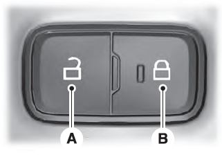
Locking and Unlocking the Doors from Inside

Locking the Doors
Press the lock switch on the door interior trim panel. The doors can no longer be released using the exterior door handle switches and the luggage compartment locks.
Copyright © 2026 www.liaviator2.com

