Lincoln Aviator 2020-2026 Service Manual / Body and Paint / Body and Paint / Third Row Seats / Removal and Installation - Third Row Seat Backrest Cover
Lincoln Aviator: Third Row Seats / Removal and Installation - Third Row Seat Backrest Cover
Special Tool(s) / General Equipment
| Flat-Bladed Screwdriver | |
| Interior Trim Remover |
Removal
NOTE: LH (left hand) shown, RH (right hand) similar.
-
Remove the third row seat backrest.
Refer to: Third Row Seat Backrest (501-10C Third Row Seats, Removal and Installation).
-
-
Release the spring tension.
Use the General Equipment: Flat-Bladed Screwdriver
-
Remove the third row head restraint pad.
-
Release the spring tension.
.jpg) |
-
Release the tabs and remove the manual head restraint release handle bezel.
.jpg) |
-
Detach the J-clip from the third row seat frame.
.jpg) |
-
Release the third row seat backrest cover J-clip.
.jpg) |
-
Release the tabs and remove the child safety seat tether anchor bezel.
Use the General Equipment: Interior Trim Remover
.jpg) |
-
NOTICE: Use care when separating the backrest cover from the hook-and-loop strips or the hook-and-loop strips may be torn from the backrest foam.
Remove the third row seat backrest cover.
-
Roll the backrest cover up while detaching the hook-and-loop strips.
-
Route the manual head restraint release strap through the backrest cover.
-
Roll the backrest cover up while detaching the hook-and-loop strips.
.jpg) |
Installation
-
To install, reverse the removal procedure.
 Removal and Installation - Third Row Seat Backrest
Special Tool(s) /
General Equipment
Interior Trim Remover
Removal
WARNING:
The following procedure describes critical repair steps
required for correct seat component installation...
 Removal and Installation - Third Row Seat Cushion
Special Tool(s) /
General Equipment
Interior Trim Remover
Removal
WARNING:
The following procedure describes critical repair steps
required for correct seat component installation...
Other information:
Lincoln Aviator 2020-2026 Owners Manual: Cleaning the Windows and Wiper Blades
Car wash chemicals and environmental fallout can result in windshield and wiper blade contamination. Dirty windshield and wipers will result in poor windshield wiper operation. Keep the windshield and wiper blades clean to maintain windshield wiper performance...
Lincoln Aviator 2020-2026 Service Manual: Description and Operation - Main Control Valve Body
Item Description 1 Internal wiring harness retaining bolt 2 Internal wiring harness 3 Park lock pawl solenoid 4 Solenoid retaining plate bolts 5 Solenoid retaining plate 6 TCC solenoid 7 LPC solenoid 8 Shift solenoid retaining plate bolts 9 Shift solenoid retaining plate 10 SSD 11 SSE 12 SSB 13 SSC 14 SSF 15 SSA 16 TFT 17 Valve channel plate bolts 18 Valve channel plate 19 Lower-to-upper valve body bolts 20 Lower valve body 21 Upper valve body 22 Valve body dowel pins Lower Valve Body 1 Valve body separator plate bolts 2 Valve body separator plate 3 TCC damper 4 LPC damper assembly 5 Check valve assemblies 6 Check balls (quantity 5) 7 LPC anti-backflow valve assembly 8 TCC priority valve assembly 9 Park lock pawl valve 10 A clutch control valve 11 SSA 12 F clutch control valve 13 SSF 14 C clutch control valve 15 SSC 16 B clutch control valve 17 SSB 18 E clutch control valve 19 SSE 20 D clutch control valve 21 SSD 22 Shift solenoid retainers Upper Valve Body 1 Lube control valve assembly 2 Plug and spring assembly 3 C clutch latch valve assembly 4 B clutch latch valve assembly 5 F clutch latch valve assembly 6 A clutch latch valve assembly 7 Plug and spring assembly 8 TCC regulator valve assembly 9 Main regulator valve assembly The main control consists of a upper and lower valve body with solenoids that are controlled by a remote mounted TCM or the PCM...
Categories
- Manuals Home
- Lincoln Aviator Owners Manual
- Lincoln Aviator Service Manual
- Fuel Quality
- Tire Change Procedure
- Anti-Theft Alarm
- New on site
- Most important about car
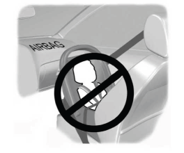
Children and Airbags
WARNING: Airbags can kill or injure a child in a child restraint. Never place a rear-facing child restraint in front of an active airbag. If you must use a forward-facing child restraint in the front seat, move the seat upon which the child restraint is installed all the way back.

Copyright © 2026 www.liaviator2.com
