
Lincoln Aviator 2020-2026 Service Manual / Chassis / Driveline
Lincoln Aviator: Chassis / Driveline
- Driveshaft
- Rear Drive Axle/Differential
- Front Drive Axle/Differential
- Front Drive Halfshafts
- Rear Drive Halfshafts
 Removal and Installation - Vehicle Dynamics Control Module (VDM)
Special Tool(s) /
General Equipment
Interior Trim Remover
Removal
NOTICE:
Electronic modules are sensitive to static electrical charges. If exposed to these charges, damage may result...
 Driveshaft
..
Other information:
Lincoln Aviator 2020-2026 Service Manual: Removal and Installation - Rear Door Window Regulator and Motor
Special Tool(s) / General Equipment Punch Removal NOTE: Left hand (LH) shown, right hand (RH) similar. NOTE: For rear door window regulator motors that are non-functional it will be necessary to remove the rear door window regulator motor prior to removing the rear door window regulator...
Lincoln Aviator 2020-2026 Service Manual: Removal and Installation - Passenger Side Register Air Discharge Temperature Sensor
Special Tool(s) / General Equipment Interior Trim Remover Removal Release the clips and remove the insutment panel speaker grille. Use the General Equipment: Interior Trim Remover Remove the bolts and the instrument panel speaker...
Categories
- Manuals Home
- Lincoln Aviator Owners Manual
- Lincoln Aviator Service Manual
- Opening and Closing the Hood
- Resetting the System
- Description and Operation - Jacking and Lifting
- New on site
- Most important about car
Locking and Unlocking the Doors from Inside
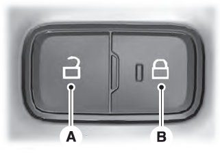
Locking the Doors
Press the lock switch on the door interior trim panel. The doors can no longer be released using the exterior door handle switches and the luggage compartment locks.

Copyright © 2026 www.liaviator2.com