Lincoln Aviator 2020-2026 Service Manual / Chassis / Suspension / Suspension System - General Information / General Procedures - Ride Height Measurement
Lincoln Aviator: Suspension System - General Information / General Procedures - Ride Height Measurement
Special Tool(s) / General Equipment
| Surface Gauge |
Check
NOTE: Make sure that the vehicle is positioned on a flat, level surface and the tires are inflated to the correct pressure. Vehicle should have a full tank of fuel.
-
Before measuring ride height check:
-
Tires are inflated to the correct pressure.
-
Vehicle should have a full tank of fuel.
-
All fluids at proper levels.
-
No cargo inside the cab or bed.
-
Inspect for aftermarket equipment. Check for
aftermarket changes to the steering, suspension, wheel and tire
components (such as competition, heavy duty, etc.).
-
Tires are inflated to the correct pressure.
-
Jounce front and rear suspension vigorously to allow the vehicle to settle.
Ride Height Measurement — Front
-
-
Ride height = 3-2
-
Measure the distance between the flat level
surface and the center of the rear control arm ball joint cap
(measurement 2)
-
Measure the distance between the flat level
surface and the center of the rear control arm inboard bolt (measurement
3)
Use the General Equipment: Surface Gauge
-
Ride height = 3-2
.jpg) |
-
With the surface gauge positioned on a flat, level
surface, record the measurement of the surface gauge position
(measurement 2) and (measurement 3).
Use the General Equipment: Surface Gauge
.jpg) |
-
Subtract measurement 2 from measurement 3 to obtain the front ride height.
Ride Height Measurement — Rear
-
-
Ride height = 2-3
-
Measurement 2
-
Measurement 3
Use the General Equipment: Surface Gauge
-
Ride height = 2-3
.jpg) |
-
Measure the distance between the flat level surface
and the center of the toe link inboard cam bolt (measurement 2).
-
Measure the distance between the flat level surface
and the center of the toe link outboard bolt (measurement 3).
-
Subtract measurement 3 from measurement 2 to obtain the rear ride height.
 General Procedures - Rear Toe Adjustment
Special Tool(s) /
General Equipment
Wheel Alignment System
Adjustment
NOTICE:
Do not use any tools or equipment to move the wheel and tire
assembly or suspension components while checking for relative movement...
Other information:
Lincoln Aviator 2020-2026 Service Manual: Removal and Installation - Front Controls Interface Module B (FCIMB)
Removal NOTE: Removal steps in this procedure may contain installation details. NOTE: If installing a new module, it is necessary to upload the module configuration information to the scan tool prior to removing the module. This information must be downloaded into the new module after installation...
Lincoln Aviator 2020-2026 Owners Manual: Child Safety Locks
When the child safety locks are set, you cannot open the rear doors from the inside. The child safety lock control is on the driver door. Press the control to switch the child safety locks on. Press the control again to switch them off. A light on the child safety control illuminates when you switch them on...
Categories
- Manuals Home
- Lincoln Aviator Owners Manual
- Lincoln Aviator Service Manual
- Changing the Front Wiper Blades - Vehicles With: Heated Wiper Blades
- Keyless Entry
- Locking and Unlocking
- New on site
- Most important about car
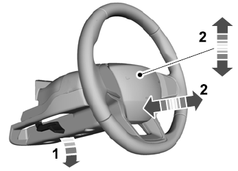
Adjusting the Steering Wheel - Vehicles With: Manual Adjustable Steering Column
WARNING: Do not adjust the steering wheel when your vehicle is moving.
Note: Make sure that you are sitting in the correct position.
Unlock the steering column. Adjust the steering wheel to the desired position.
Copyright © 2026 www.liaviator2.com

