
Lincoln Aviator: Seats / Head Restraints
WARNING: Fully adjust the head restraint before you sit in or operate your vehicle. This will help minimize the risk of neck injury in the event of a crash. Do not adjust the head restraint when your vehicle is moving.
WARNING: The head restraint is a safety device. Whenever possible it should be installed and properly adjusted when the seat is occupied. Failure to adjust the head restraint properly could reduce its effectiveness during certain impacts.
Note: Adjust the seat backrest to an upright driving position before adjusting the head restraint. Adjust the head restraint so that the top of it is level with the top of your head and as far forward as possible. Make sure that you remain comfortable. If you are extremely tall, adjust the head restraint to its highest position.
Adjusting the Head Restraints
Front Seat Head Restraints
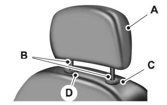
- The head restraints consist of:
- An energy absorbing head restraint.
- Two steel stems.
- Guide sleeve adjust and release button.
- Guide sleeve unlock and remove button.
Raising the Head Restraint
Pull the head restraint up.
Lowering the Head Restraint
- Press and hold the C button.
- Push the head restraint down.
Removing the Head Restraint
- Pull the head restraint up until it reaches its highest position.
- Press and hold the C and D buttons.
- Pull the head restraint up.
Installing the Head Restraint
Align the steel stems into the guide sleeves and push the head restraint down until it locks.
Tilting Head Restraints
The front head restraints tilt for extra comfort. To tilt the head restraint, do the following:
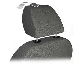
- Adjust the seat backrest to an upright driving or riding position.
- Pivot the head restraint forward toward your head to the position you prefer.
After the head restraint reaches the forward-most tilt position, pivot it forward again to release it to the rearward, un-tilted position.
Second Row Center Seat Head Restraint (If Equipped)
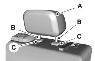
The head restraints consist of:
- An energy absorbing head restraint.
- Two steel stems.
- Guide sleeve adjust and release buttons.
Raising the Head Restraint
Pull the head restraint up.
Lowering the Head Restraint
- Press and hold the C buttons.
- Push the head restraint down.
Second Row Outermost Seat Head Restraints
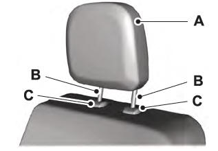
The head restraints consist of:
- An energy absorbing head restraint.
- Two steel stems.
- Guide sleeve unlock and remove button.
Removing the Head Restraint
- Press and hold the C buttons.
- Pull the head restraint up.
Installing the Head Restraint
Align the steel stems into the guide sleeves and push the head restraint down until it locks.
Third Row Seat Head Restraints
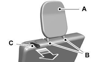
The head restraints consist of:
- An energy absorbing head restraint.
- Two steel stems.
- Fold strap.
Folding the Head Restraint
Pull the fold strap (C). Pull the head restraint back up to reset.
Power Front Head Restraints (If equipped)
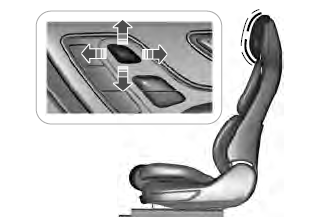
To raise the head restraint, lift the switch up until you reach a comfortable height.
To lower the head restraint, press the switch down.
To move the head restraint forward, push the switch forward until you reach the desired position.
To move the head restraint rearward, push the switch rearward.
 Sitting in the Correct Position
WARNING: Sitting improperly, out of
position or with the seatback reclined too
far can take weight off the seat cushion
and affect the decision of the passenger
sensing system, resulting in serious injury
or death in the event of a crash...
 Power Seats
WARNING: Do not adjust the driver
seat or seat backrest when your vehicle is
moving. This may result in sudden seat
movement, causing the loss of control of
your vehicle...
Other information:
Lincoln Aviator 2020-2026 Service Manual: Removal and Installation - Engine Mount LH
Special Tool(s) / General Equipment 303-050 (T70P-6000) Lifting Bracket, Engine 303-F070Support Bar, EngineTKIT-1999A-F/LTTKIT-1999A-FM/FLM Removal NOTE: AWD shown, RWD similar. With the vehicle in NEUTRAL, position it on a hoist...
Lincoln Aviator 2020-2026 Service Manual: Removal and Installation - Passenger Side Register Air Discharge Temperature Sensor
Special Tool(s) / General Equipment Interior Trim Remover Removal Release the clips and remove the insutment panel speaker grille. Use the General Equipment: Interior Trim Remover Remove the bolts and the instrument panel speaker...
Categories
- Manuals Home
- Lincoln Aviator Owners Manual
- Lincoln Aviator Service Manual
- Child Safety Locks
- Fuel Quality
- Locking and Unlocking
- New on site
- Most important about car
Emergency Locking
Each door has a backup power system which allows the door to function if your vehicle has no power. The system has a limited number of operations before the power is depleted and turns off. When the system turns off, the door remains open and unlatched and does not close.
If your vehicle has no power and the backup power system is turned off, you can close and secure your vehicle by manually resetting each door latch using a key in the position shown.
