Lincoln Aviator: Opening and Closing the Liftgate, Stopping the Liftgate Movement / Opening and Closing the Liftgate
WARNING: Make sure all persons are clear of the power liftgate area before using the power liftgate control.
Note: Make sure the area behind your vehicle is free from obstruction and that there is enough room for you to operate the liftgate. Make sure the area behind your vehicle is free from obstruction and that there is enough room for you to operate the liftgate.
Note: Be careful when opening or closing the liftgate in a garage or other enclosed area to avoid damaging the liftgate.
Note: Do not leave the liftgate open when you are driving. This could damage the liftgate and its components.
Opening from the Instrument Panel
 With the transmission in park
(P),
press the button on the instrument
panel.
With the transmission in park
(P),
press the button on the instrument
panel.
Opening with the Remote Control
 Press the button twice within
three
seconds.
Press the button twice within
three
seconds.
Opening with the Outside Control Button
- Unlock the liftgate with the remote
control or power door unlock control. If
a passive key is within 3 ft (1 m) of the
liftgate, the liftgate unlocks when you
press the liftgate release button.
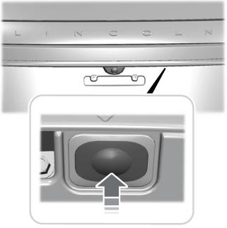
- Press the control button to the right of the rear view camera.
Note: Allow the power system to open the liftgate. Manually pushing or pulling the liftgate could activate the system’s obstacle detection feature and stop the power operation or reverse its direction, replicate a strut failure, or damage mechanical components.
Closing the Liftgate
WARNING: Keep clear of the liftgate when using the rear switch.
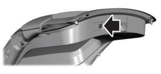
Press and release the liftgate button.

 Stopping the Liftgate Movement
Note: Do not apply sudden excessive force
to the liftgate while it is in motion. This could
damage the power liftgate and its
components.
You can stop the liftgate movement by doing
any of the following:
Pressing the liftgate control button...
Other information:
Lincoln Aviator 2020-2026 Owners Manual: Keyless Starting
Note: The system may not function if the remote control is close to metal objects or electronic devices, for example keys or a cell phone. Note: A valid remote control must be located inside your vehicle to switch the ignition on and start your vehicle...
Lincoln Aviator 2020-2026 Service Manual: Removal and Installation - Reversing Lamp
Removal NOTE: Removal steps in this procedure may contain installation details. Remove the liftgate trim panel. Refer to: Liftgate Trim Panel (501-05 Interior Trim and Ornamentation, Removal and Installation). Disconnect the reversing lamp assembly camera washer fluid hose and connectors...
Categories
- Manuals Home
- Lincoln Aviator Owners Manual
- Lincoln Aviator Service Manual
- Tire Change Procedure
- Description and Operation - Jacking and Lifting
- Anti-Theft Alarm
- New on site
- Most important about car
Activating Intelligent Access
The intelligent access key must be within 3 ft (1 m) of the door or luggage compartment you intend to lock or unlock.
At a Door
Electronic door handles are on each door. Gently depress the switch inside the exterior door handle to unlock and open the door. An unlock symbol illuminates on the door window trim indicating your vehicle is unlocked.
