Lincoln Aviator: Automatic Transmission - 10-Speed Automatic Transmission – 10R60 / Overhaul - Transmission
Special Tool(s) /
General Equipment
.jpg) |
100-001
(T50T-100-A)
Slide Hammer |
.jpg) |
100-002
(TOOL-4201-C)
Holding Fixture with Dial Indicator Gauge |
.jpg) |
205-1018
Installation Tube |
 |
307-003
(T57L-500-B)
Holding Fixture, Transmission |
 |
307-091
Handle, Torque Converter
TKIT-2009TC-F |
 |
307-309
Remover, Torque Converter Seal
TKIT-1994-FMH/FLMH
TKIT-1994-LMH/MH
TKIT-1994-FH |
.jpg) |
307-346
(T97T-7902-A)
Retainer, Torque Converter
TKIT-1998-LM (NavigatoR)
TKIT-1997-F/FLM/LT |
 |
307-549
Installer, Shift Shaft Fluid Seal
TKIT-2005D1-F1 |
.jpg) |
307-584
2-6 Spring Compressor
TKIT-2006UF-FLM
TKIT-2006UF-ROW |
.jpg) |
307-589
Overdrive clutch and balance piston service set
TKIT-2006UF-FLM
TKIT-2006UF-ROW |
 |
307-651
Bracket, Pump Remover/Installer |
.jpg) |
307-651-02
Lift fixture adapter for 307-651 |
 |
307-661
Gauge, End Play
TKIT-2009C-F
TKIT-2009C-ROW |
.jpg) |
307-661-01
Spacers/Plate, Clearance Gage |
.jpg) |
307-662
Gauge, Clutch Pack Endplay
TKIT-2009C-F
TKIT-2009C-ROW |
 |
307-691
Tester, Torque Convertor Leak |
.jpg) |
307-732
Tool Kit, Torque Converter Flusher |
.jpg) |
307-732-02
Adapter for 307-732 Converter flushing Mandrel |
 |
307-736
Installer, Pump Drive Gear Bearing |
 |
307-737
Press Tool, Oil Pump Drive Idler Gear |
.jpg) |
307-741
Spring Compressor, F Clutch |
 |
307-743
Remover, Pump Drive Gear |
.jpg) |
307-746
Remover, Transmission Wiring Harness Connector |
 |
307-780
Converter Seal installer |
.jpg) |
307-782
Installer, Output Shaft Seal |
 |
307-783
Installer, Roll Pin |
.jpg) |
307-784
One way clutch alignment tool |
.jpg) |
307-785
Clutch spring compressor |
 |
307-786
F7 Seal Installer/Sizer Input Shaft |
 |
307-787
F8 Seal Installer/Sizer Input Shaft |
 |
307-790
Endplay Check Gauge |
 |
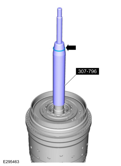
307-796
F2 Seal Guide, Installer & Sizer |
.jpg) |
307-797
Installer, Alignment Studs (3) & Alignment Pin (All 10R) |
 |
307-803
F1 Seal Guide, Installer & Sizer |
 |
307-804
F9 Seal Guide, Installer & Sizer |
| Rubber Mallet |
| Hydraulic Press |
| Punch |
| Wooden Block |
| Magnet |
Materials
| Name |
Specification |
Motorcraft® MERCON® ULV Automatic Transmission Fluid
XT-12-QULV |
WSS-M2C949-A,
MERCON® ULV
|
All vehicles
-
Transmission overhaul includes the following:
-
Complete disassembly of the transmission
-
Cleaning and inspecting of all components
-
Replacement of all seals, gaskets, and one time use components. Use gasket kit -7153-
-
Complete assembly with clearances adjusted to specification
-
Replacement of any additional parts that may be required if worn or damaged
-
For information on component views and base part numbers.
Refer to: Transmission Description (307-01A Automatic Transmission - 10-Speed Automatic Transmission – 10R60, Description and Operation).
-
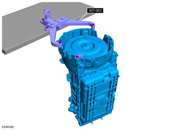
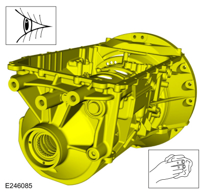
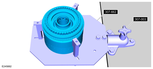
Using the special tool, install the transmission on a bench.
Use Special Service Tool: 307-003
(T57L-500-B)
Holding Fixture, Transmission.
-
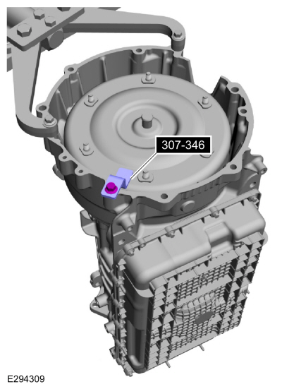
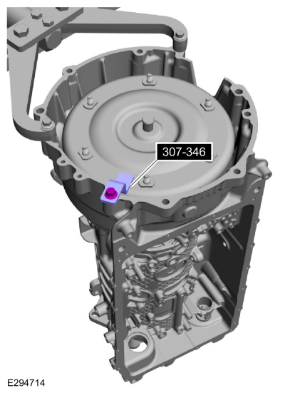
Remove the special tool.
Use Special Service Tool: 307-346
(T97T-7902-A)
Retainer, Torque Converter.
-
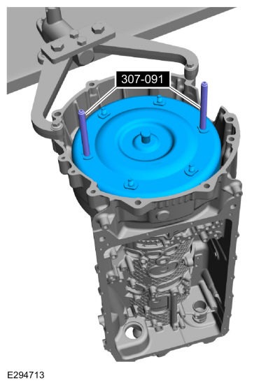
Using the special tool, remove the torque converter.
Use Special Service Tool: 307-091
Handle, Torque Converter.
-
A new or remanufactured torque converter must be installed if one or more of the following statements are true:
-
The sealing surface has a groove worn from the seal.
-
A torque converter malfunction has been determined based on complete diagnostic procedures.
-
The torque converter stud or studs, threaded pads, impeller hub or bushing are damaged.
-
The torque converter exhibits external discoloration (due to overheating).
-
There is evidence of water or antifreeze contamination.
Flush The Torque Converter With The Transmission Cooling System Heated Flusher
-
NOTE:
Use transmission fluid specified for this
transmission. Do not use any supplemental transmission fluid additives
or cleaning agents. The use of these products could cause internal
transmission components to fail, which will affect the operation of the
transmission.
The torque converter must be flushed every time the
transmission is overhauled. It is mandatory that proper equipment and
procedures be followed when flushing the torque converter. The flushing
equipment used MUST:
-
Maintain the transmission fluid at 140°F or above
-
Pulsate the transmission fluid during cleaning
-
Have a filter with a rating of 100 micron or less
-
Have air purge capability before and after flushing
-
If equipment meeting the specifications above is not
available, the torque converter must be flushed by hand. Go to Flush The
Torque Converter By Hand steps later in this procedure.
-
Check and top off the transmission fluid level of the
transmission cooling system heated flusher with transmission fluid.
-
Turn on the heater and allow the transmission fluid in
the transmission cooling system heated flusher 15-30 minutes to heat up
to 60°C (140°F) before using.
-
Place the torque converter in an arbor press. Support the torque converter on the mounting pads.
-
-
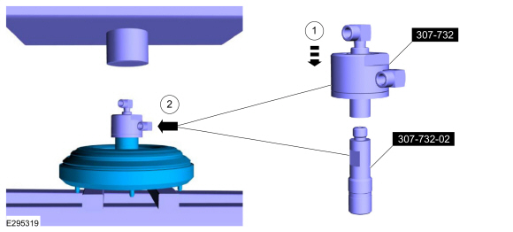
Assemble the special tools.
Use Special Service Tool: 307-732
Tool Kit, Torque Converter Flusher.
, 307-732-02
Adapter for 307-732 Converter flushing Mandrel.
-
Install the special tools on the torque converter hub.
-
Using the special tool, install the slotted cap.
Use Special Service Tool: 307-691
Tester, Torque Convertor Leak.
-
Apply enough force from the press to seal the torque converter flush main hub to the torque converter hub.
-
Connect the flush machine to the main hub.
-
Red hose on top.
-
Blue hose on bottom.
-
Follow the equipment instructions to purge transmission
fluid from the torque converter prior to starting the flushing
procedure.
-
.jpg) WARNING:
The torque converter, adaptor 307-732, and the hoses will be hot.
WARNING:
The torque converter, adaptor 307-732, and the hoses will be hot.
NOTE:
Maintain visual contact with torque converter during
the entire flush procedure. Immediately stop the flush machine if a
leak develops. Repeat set up steps to reseal the tool to the converter
hub and continue flushing.
Forward flush the converter for 15 minutes.
-
Monitor GPM flow meter periodically during the flush
procedure. Flow rate above 2.0 gallons per minute is required to break
up and dislodge any contamination trapped behind the TCC plate. Service flush machine filter(s) if flow rate drops below 2 GPM.
-
Follow the equipment instructions to purge the torque converter.
-
WARNING:
The torque converter, adaptor 307-732, and the hoses will be hot.
Allow torque converter and equipment to cool for 30 minutes before handling.
-
Disconnect the hoses and remove the special tools.
Flush The Torque Converter By Hand
NOTICE:
Do not use water-based cleaners or mineral spirits to clean
or flush the torque converter or transmission damage will occur. Use
only clean transmission fluid designated for the transmission and torque
converter being serviced.
NOTE:
Only flush the torque converter by hand when the transmission cooling system heated flusher is not available.
-
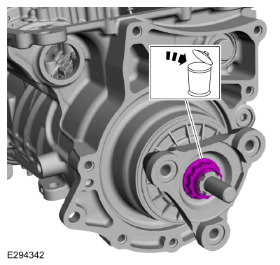
Pour a small amount of transmission fluid from the
torque converter onto an absorbent white tissue or through a paper
filter.
-
Examine the transmission fluid for contaminants. The
transmission fluid must be free of metallic contaminants. If metallic
contaminants are present, do not continue with hand flushing. The torque
converter must be flushed with the transmission cooling system heated
flusher.
-
Drain the remaining transmission fluid from the torque converter.
-
Using only the recommended transmission fluid, add 1.9L
(2 qt) of clean transmission fluid into the converter and agitate by
hand.
Material: Motorcraft® MERCON® ULV Automatic Transmission Fluid
/ XT-12-QULV
(WSS-M2C949-A, )
(MERCON® ULV)
-
Thoroughly drain the transmission fluid.
All vehicles
-
NOTE:
Note the location of the studbolts and bolts for assembly.
Remove the studbolts and bolts and the transmission fluid pan.
-
Studbolts
-
Bolts
-
NOTE:
The transmission fluid pan gasket can be reused if not damaged.
NOTE:
Note the location of the alignment tabs.
Remove the transmission fluid pan gasket.
-
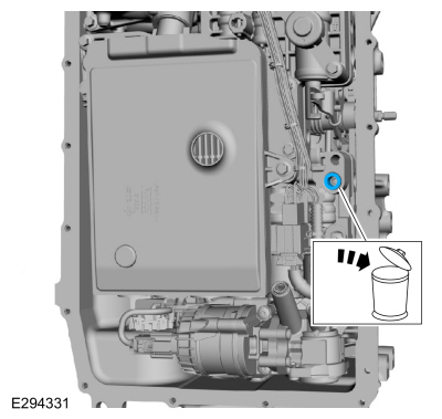
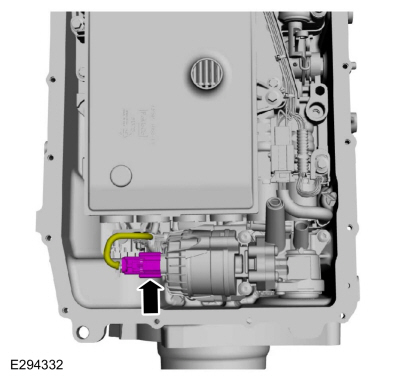
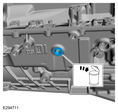
Remove the plug and transmission fluid level indicator assembly.
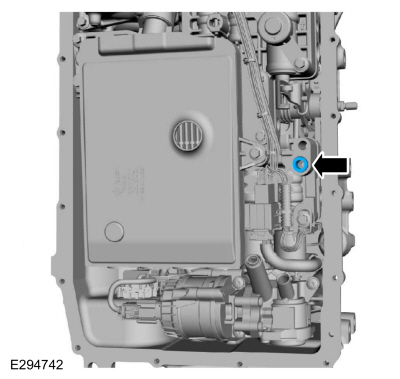
Auto-Start-Stop vehicles
-
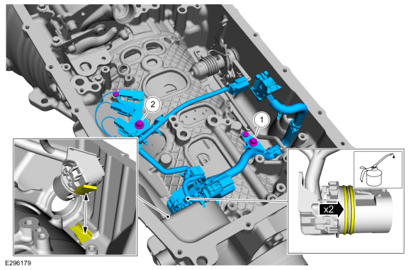
Remove the bolt and the transmission fluid auxiliary pump tube.
-
Remove and discard the transmission fluid auxiliary pump tube seal.
-
Disconnect the transmission fluid auxiliary pump electrical connector.
-
NOTE:
If the transmission fluid was contaminated from a
catastrophic failure, replace the transmission fluid auxiliary pump.
Remove the bolts and the transmission fluid auxiliary pump.
All vehicles
-
NOTE:
The transmission fluid filter may be reused if no excessive contamination is indicated.
Remove the 71 mm and 20 mm bolts and the transmission fluid filter.
-
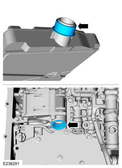
NOTE:
The transmission fluid filter seal will either come
off with the transmission fluid filter or it will be stuck in the pump.
Remove the transmission fluid filter seal.
-
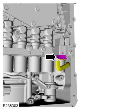
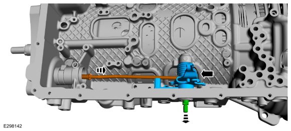
Disconnect the main control main electrical connector.
-
Remove the nut and the park override lever.
-
Rotate the manual shaft to the park override position.
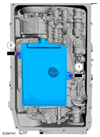
-
-
Remove the 68 mm bolts and the main control assembly.
-
Check to see if the main control-to-transmission fluid pump seal is attached to the main control.
-
Clean and inspect the main control for damage.
Refer to: Main Control Valve Body (307-01A Automatic Transmission - 10-Speed Automatic Transmission – 10R60, Overhaul).
-
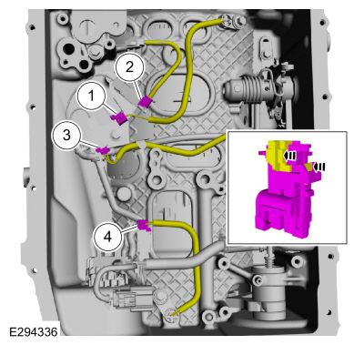
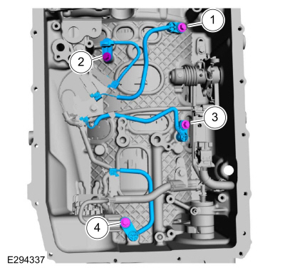
Unlock and disconnect the speed sensors.
-
Intermediate Speed Sensor A (ISSA)
-
TSS sensor
-
Intermediate Speed Sensor B (ISSB)
-
OSS sensor
-
Remove the speed sensors.
-
Intermediate Speed Sensor A (ISSA)
-
TSS sensor
-
Intermediate Speed Sensor B (ISSB)
-
OSS sensor
-
Disconnect the TR sensor electrical connector.
-
Using the special tool, disconnect the transmission
internal wiring harness connector from the transmission case.
-
Slide the special tool over the connector flush with the transmission case.
Use Special Service Tool: 307-746
Remover, Transmission Wiring Harness Connector.
-
Use the special tool to push the connector through the case.
-
Remove the bolts and the transmission internal wiring harness.
-
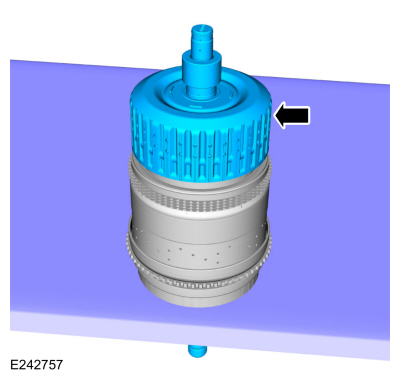
Remove the bolts and the transmission fluid pump.
-
-
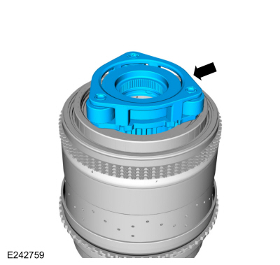
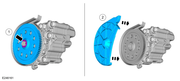
Remove the transmission fluid pump driven gear outer cover.
-
Clean and inspect the transmission fluid pump driven gear.
-
If replacing the transmission fluid pump driven gear
or transmission fluid pump driven gear inner cover, remove the
retaining ring and the transmission fluid pump driven gear.
-
If necessary, remove the bolts and the transmission fluid pump driven gear inner cover.
Rear Wheel Drive (RWD) vehicles
-
Remove the stakes from the output shaft flange retaining nut.
Use the General Equipment: Punch
-
Remove and discard the output shaft flange nut.
-
-
Index mark the output shaft to the flange.
-
Remove the output shaft flange.
All vehicles
-
Using a punch, remove and discard the manual shaft-to-TR sensor roll pin.
Use the General Equipment: Punch
-
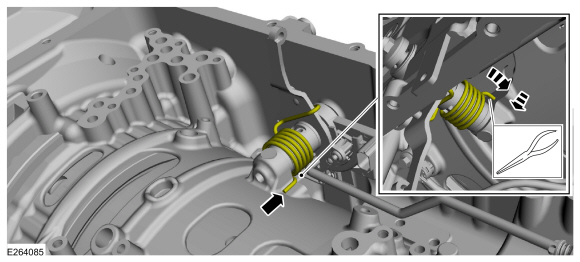
Release the tension from the park return spring.
-
Slide the end of the park return spring off the transmission case.
-
Remove the manual shaft, the TR sensor and the park pawl actuator rod.
-
Remove and discard the manual control shaft seal.
-
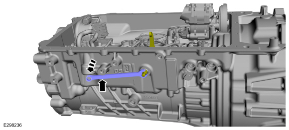
Remove the bolt and the TR sensor detent spring.
-
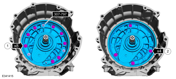
Rotate the transmission to a vertical position. Remove the front support assembly bolts.
-
-
NOTE:
Front support bolts with External Torx Plus® Low Profile (EPL) bolt heads may be reused.
Remove and discard the seals.
-
NOTE:
Front support bolts with external hex flange heads with sealant on the flange are not reusable.
Discard the bolts.
-
NOTICE:
Be careful not to contact the transmission fluid pump drive gear, or damage to the gear can occur.
Using a prybar, pry the front support assembly out of
the transmission case and remove the front support assembly.
-
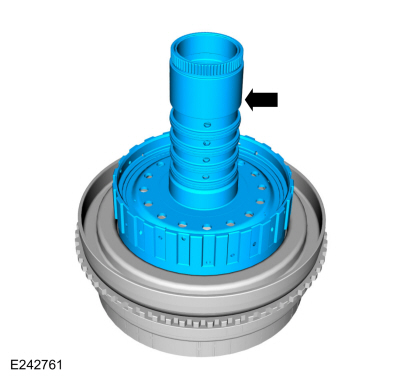
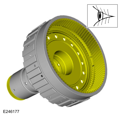
Using the special tools and a floor crane, remove the clutch and planetary assembly.
Use Special Service Tool: 307-651
Bracket, Pump Remover/Installer.
, 307-651-02
Lift fixture adapter for 307-651.
-
Remove the (T9) thrust bearing.
-
Remove the output shaft and planetary carrier No. 4 assembly.
-
Remove and discard the output shaft seals.
-
Remove the (T10) thrust bearing.
-
Clean and inspect the output shaft and planetary carrier No. 4 assembly.
-
Using the special tools, remove and discard the output shaft seal.
Use Special Service Tool: 100-001
(T50T-100-A)
Slide Hammer.
, 307-309
Remover, Torque Converter Seal.
Rear Wheel Drive (RWD) vehicles
-
Remove the anti-ting washer.
All vehicles
-
NOTE:
Rear Wheel Drive (RWD) transmission case ball
bearings cannot be serviced separately. They can only be serviced as a
case and bearing assembly.
Clean and inspect the transmission case and bearings.
Check for leaks from plugs and park pawl actuator rod sleeve. Repair or
replace as necessary.
Refer to: Transmission Case (307-01A Automatic Transmission - 10-Speed Automatic Transmission – 10R60, Disassembly).
-
NOTICE:
If replacing A clutch separating springs, all
separating springs must be replaced as a matching set or damage can
occur.
Remove the A clutch assembly. Inspect the clutch plates
for excessive wear or damage. If the clutch plates are excessively worn
or damaged replace as necessary. If the clutch plates are not
excessively worn or damaged, they can be reused.
-
Using a magnet, remove the selective shim and the (T3) thrust bearing.
Use the General Equipment: Magnet
-
Remove and discard the input shaft front Teflon® seals.
-
Remove one side of the No. 1 planetary carrier snap ring.
-
Flip the clutch and planetary assembly over with the
input shaft through a hole in the bench. Remove the No. 1 planetary
carrier snap ring and remove the clutch and planetary container
cylinder.
-
-
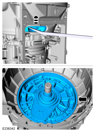
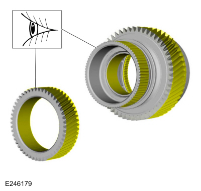
Inspect the No. 4 ring gear.
-
NOTE:
Remove the ring gear when replacement is necessary.
If necessary, remove the ring gear snap ring.
-
If necessary, remove the ring gear from the inside of the clutch and planetary container cylinder.
-
Remove the (T8) thrust bearing.
-
Remove the E clutch and input shaft assembly.
-
Remove the No. 3 planetary carrier and the No. 3 sun gear.
-
Inspect the No. 3 planetary carrier and the No. 3 sun gear.
-
Remove the CDF clutch assembly from the planetary carrier assembly.
-
Remove the No. 3 sun gear shaft and No. 2 ring gear assembly.
-
Inspect the No. 3 sun gear shaft and No. 2 ring gear assembly.
-
Remove the (T5) thrust bearing.
-
Remove the No. 2 planetary carrier.
-
NOTE:
It is not necessary to remove the fluid collectors from the No. 2 planetary carrier.
Inspect the No. 2 planetary carrier and the fluid collectors.
-
Fluid collectors
-
Remove the No. 2 sun gear.
-
Remove the No. 1 sun gear.
-
Inspect the No. 1 and No. 2 sun gears.
-
Gently pry up on the clips and remove the No. 1 bearing support locking ring.
-
Rotate the No. 1 bearing support clockwise and remove the bearing support.
-
Remove the No. 1 ring gear bearing.
-
Remove the No. 1 ring gear.
-
Remove the ring gear No 1 bearing.
-
Inspect the No. 1 ring gear and the No. 1 planetary carrier, gears, bearing and fluid collectors.
-
Install the ring gear No. 1 bearing with the flat side down.
-
Ring gear No. 1 bearing flat side
-
Install the No. 1 ring gear.
-
Install the No. 1 ring gear bearing.
-
Install the ring gear No. 1 bearing support and rotate it counter clockwise to lock it.
-
Align the tabs with the slots and install the No. 1 bearing support locking ring.
-
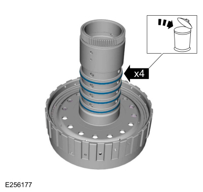
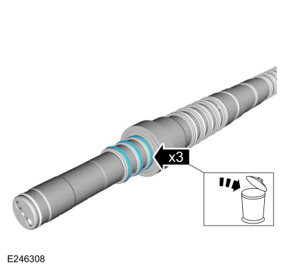
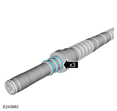
Remove and discard the sun gear No. 3 shaft Teflon® seals.
-
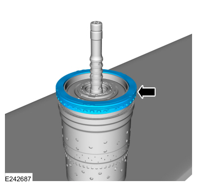
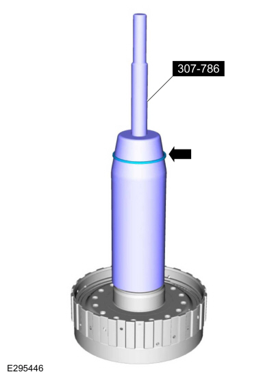
Install the special tool and adjust the special tool to
align the bottom edge of the tool with the top edge of the bottom
Teflon® seal groove.
Use Special Service Tool: 307-786
F7 Seal Installer/Sizer Input Shaft.
-
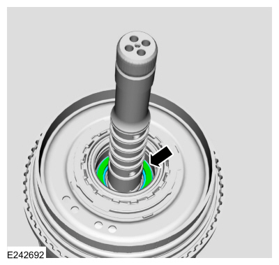
Install a new Teflon® seal on the special tool.
Use Special Service Tool: 307-786
F7 Seal Installer/Sizer Input Shaft.
-
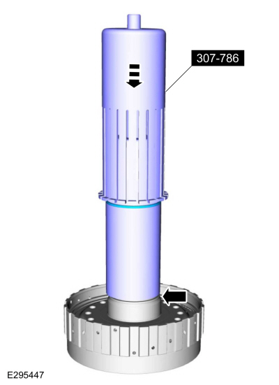
Using the top half of the special tool, slide the
Teflon® seal into the groove. Remove the special tools and repeat the
steps for the other 3 Teflon® seals.
Use Special Service Tool: 307-786
F7 Seal Installer/Sizer Input Shaft.
-
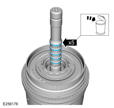
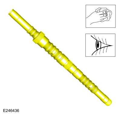
Install the special tool to size the 4 Teflon® seals.
Allow the special tool to stay on the No 3 sun gear shaft for 5 minutes
prior to final assembly.
Use Special Service Tool: 307-786
F7 Seal Installer/Sizer Input Shaft.
-
Remove the snap ring and the C clutch assembly. Inspect
the clutch plates for excessive wear or damage. If the clutch plates are
excessively worn or damaged replace as necessary. If the clutch plates
are not excessively worn or damaged, they can be reused.
-
Using the special tools and a press, remove the C clutch balance dam retainer.
Use Special Service Tool: 307-584
2-6 Spring Compressor.
, 307-589
Overdrive clutch and balance piston service set.
Use the General Equipment: Hydraulic Press
-
Remove the C clutch balance dam.
-
Remove the C clutch piston return spring.
-
Remove and discard the C clutch balance dam inner and outer seals.
-
Remove the C clutch piston. Use compressed air into one
oil passage hole while plugging the hole on the opposite side.
-
Remove and discard the C clutch piston inner and outer seals.
-
Remove the snap ring and the D clutch assembly. Inspect
the clutch plates for excessive wear or damage. If the clutch plates are
excessively worn or damaged replace as necessary. If the clutch plates
are not excessively worn or damaged, they can be reused.
-
Remove the D clutch apply ring.
-
Using the special tools and a press, remove the D clutch balance dam retainer.
Use Special Service Tool: 307-584
2-6 Spring Compressor.
, 307-589
Overdrive clutch and balance piston service set.
Use the General Equipment: Hydraulic Press
-
Remove and discard the D clutch balance dam inner and outer seals.
-
Remove the D clutch piston return spring.
-
Remove the D clutch piston. Use compressed air into one
oil passage hole while plugging the hole on the opposite side.
-
Remove and discard the D clutch piston inner and outer seals.
-
Remove the F clutch keeper snap ring, F clutch snap ring keeper and the F clutch snap ring.
-
F clutch keeper snap ring
-
F clutch snap ring keeper
-
F clutch snap ring
-
Remove the F clutch assembly. Inspect the clutch plates
for excessive wear or damage. If the clutch plates are excessively worn
or damaged replace as necessary. If the clutch plates are not
excessively worn or damaged, they can be reused.
-
Remove the F clutch apply ring.
-
Using the special tools and a press, compress the F
clutch balance dam and remove the retainer. Remove the F clutch balance
dam.
Use Special Service Tool: 307-741
Spring Compressor, F Clutch.
Use the General Equipment: Hydraulic Press
-
Remove and discard the F clutch balance dam outer seal.
-
Remove the F clutch piston return spring.
-
Remove and discard the F clutch balance dam inner seal.
-
Remove the F clutch piston.
-
Remove and discard the F clutch piston seals.
-
Clean and inspect the CDF clutch cylinder.
-
Install the new F clutch piston seals. Lubricate the seals with petroleum jelly.
-
Install the F clutch piston.
-
Install the new F clutch balance dam inner seal. Lubricate the seal with petroleum jelly.
-
Install the F clutch piston return spring.
-
Install the new F clutch balance dam outer seal. Lubricate the seal with petroleum jelly.
-
NOTE:
The F clutch balance dam retainer will not be in the groove at this time.
Install the F clutch balance dam and retainer on the CDF clutch cylinder.
-
Using the special tools and a press, compress the F clutch balance dam and install the retainer into the groove.
Use Special Service Tool: 307-741
Spring Compressor, F Clutch.
Use the General Equipment: Hydraulic Press
-
Using the special tools and a press, press the apply ring onto the F clutch piston.
-
F clutch apply ring
-
Clutch steel plate
-
NOTE:
Position the F clutch pressure plate upside-down onto the clutch steel plate.
F clutch pressure plate
Use Special Service Tool: 307-741
Spring Compressor, F Clutch.
Use the General Equipment: Hydraulic Press
-
NOTE:
Clutch plate quantity is model dependant based on engine displacement.
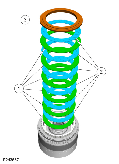
Soak the F clutch plates in clean transmission fluid. Install the F clutch assembly.
-
Steel plates
-
Friction plates
Material: Motorcraft® MERCON® ULV Automatic Transmission Fluid
/ XT-12-QULV
(WSS-M2C949-A, )
(MERCON® ULV)
-
Pressure plate
-
Install the F clutch snap ring, F clutch snap ring keeper and the F clutch keeper snap ring .
-
F clutch snap ring
-
F clutch snap ring keeper
-
F clutch keeper snap ring
-
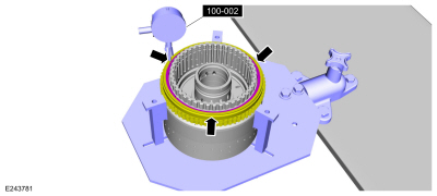
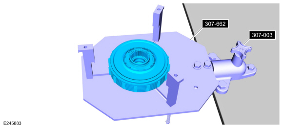
Assemble the special tools and position the CDF clutch cylinder with the F clutch facing up.
Use Special Service Tool: 307-662
Gauge, Clutch Pack Endplay.
, 307-003
(T57L-500-B)
Holding Fixture, Transmission.
-
Using the special tool, measure the F clutch clearance.
Position the plunger so it rests on the top surface of the pressure
plate. Zero the dial indicator. Pull up on the pressure plate and
measure and record the clutch clearance in 3 different places. Average
the 3 recorded clutch clearance measurements and compare the measurement
to the clutch clearance chart in specifications to determine the
correct size snap ring. Install the correct F clutch snap ring.
Use Special Service Tool: 100-002
(TOOL-4201-C)
Holding Fixture with Dial Indicator Gauge.
-
Install the new D clutch piston inner and outer seals. Lubricate the seals with petroleum jelly.
-
Install the D clutch piston.
-
Install the D clutch piston return spring.
-
Install the new D clutch balance dam inner and outer seals. Lubricate the seals with petroleum jelly.
-
Using the special tools and a press, Install the D clutch balance dam and install the retainer.
Use Special Service Tool: 307-584
2-6 Spring Compressor.
, 307-589
Overdrive clutch and balance piston service set.
Use the General Equipment: Hydraulic Press
-
Install the D clutch apply ring.
-
NOTE:
Clutch plate quantity is model dependant based on engine displacement.
Soak the D clutch plates in clean transmission fluid. Install the D clutch assembly.
-
Steel plates
-
Friction plates
Material: Motorcraft® MERCON® ULV Automatic Transmission Fluid
/ XT-12-QULV
(WSS-M2C949-A, )
(MERCON® ULV)
-
Pressure plate
-
Install the D clutch snap ring.
-
Assemble the special tools and position the CDF clutch cylinder with the D clutch facing up.
Use Special Service Tool: 307-662
Gauge, Clutch Pack Endplay.
, 307-003
(T57L-500-B)
Holding Fixture, Transmission.
-
Using the special tool, measure the D clutch clearance.
Position the plunger so it rests on the top surface of the pressure
plate. Zero the dial indicator. Pull up on the pressure plate and
measure and record the clutch clearance in 3 different places. Average
the 3 recorded clutch clearance measurements and compare the measurement
to the clutch clearance chart in specifications to determine the
correct size snap ring. Install the correct D clutch snap ring.
Use Special Service Tool: 100-002
(TOOL-4201-C)
Holding Fixture with Dial Indicator Gauge.
-
Install the new C clutch piston inner and outer seals. Lubricate the seals with petroleum jelly.
-
Install the C clutch piston.
-
Install the new C clutch balance dam seals. Lubricate the seals with petroleum jelly.
-
Install the C clutch piston return spring.
-
Install the C clutch balance dam.
-
Using the special tools and a press, compress the C clutch balance dam and install the retainer.
Use Special Service Tool: 307-584
2-6 Spring Compressor.
, 307-589
Overdrive clutch and balance piston service set.
Use the General Equipment: Hydraulic Press
-
NOTE:
Clutch plate quantity is model dependant based on engine displacement.
Soak the C clutch plates in clean transmission fluid. Install the C clutch assembly.
-
Steel plates
-
Friction plates
Material: Motorcraft® MERCON® ULV Automatic Transmission Fluid
/ XT-12-QULV
(WSS-M2C949-A, )
(MERCON® ULV)
-
Pressure plate
-
Install the C clutch snap ring.
-
Assemble the special tools and position the CDF clutch cylinder with the C clutch facing up.
Use Special Service Tool: 307-662
Gauge, Clutch Pack Endplay.
, 307-003
(T57L-500-B)
Holding Fixture, Transmission.
-
Using the special tool, measure the C clutch clearance.
Position the plunger so it rests on the top surface of the pressure
plate. Zero the dial indicator. Pull up on the pressure plate and
measure and record the clutch clearance in 3 different places. Average
the 3 recorded clutch clearance measurements and compare the measurement
to the clutch clearance chart in specifications to determine the
correct size snap ring. Install the correct C clutch snap ring.
Use Special Service Tool: 100-002
(TOOL-4201-C)
Holding Fixture with Dial Indicator Gauge.
-
NOTE:
Pry up from the 2 tabs to prevent the bearing from separating.
Remove the (T6) thrust bearing.
-
Remove the snap ring and the No. 3 ring gear.
-
Remove the rear No. 3 ring gear snap ring.
-
Inspect the No. 3 ring gear.
-
Remove the input shaft and the E clutch from No. 4 shell and sun gear.
-
Inspect the No. 4 shell and sun gear.
-
NOTE:
Pry up from the 2 tabs to prevent the bearing from separating.
Remove the (T7) thrust bearing.
-
Remove the snap ring and remove the input shaft from the E clutch assembly.
-
Remove and discard the input shaft-to-sun gear No. 3 shaft Teflon® seals.
-
Remove and discard the input shaft O-ring seals.
-
Remove and discard the input shaft Teflon® seal.
-
Clean and inspect the input shaft.
-
NOTICE:
Do not compress the balance dam too far or damage to
the E clutch hub can occur. Only compress the E clutch hub far enough
to remove the retainer.
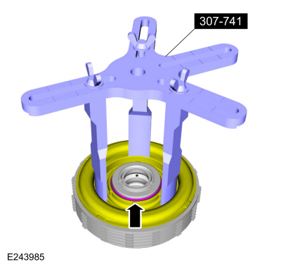
Using the special tool and a press, compress the E clutch balance dam and remove the retainer.
Use Special Service Tool: 307-741
Spring Compressor, F Clutch.
Use the General Equipment: Hydraulic Press
-
Pry the E clutch piston and balance dam upward and remove the piston and balance dam from the E clutch hub.
-
Remove the E clutch balance dam and discard the E clutch piston.
-
E clutch balance dam
-
E clutch piston
-
Remove and discard the E clutch balance dam outer seal.
-
Remove the E clutch piston return spring.
-
Remove the E clutch assembly. Inspect the clutch plates
for excessive wear or damage. If the clutch plates are excessively worn
or damaged replace as necessary. If the clutch plates are not
excessively worn or damaged, they can be reused.
-
Remove and discard the E clutch piston and balance dam inner seals.
-
Clean and inspect the E clutch hub.
-
Install the new E clutch piston and balance dam inner seals. Lubricate the seals with petroleum jelly.
-
NOTE:
Clutch plate quantity is model dependant based on engine displacement.
Soak the E clutch plates in clean transmission fluid. Install the E clutch assembly.
-
Pressure plate (select fit)
-
Friction plates
Material: Motorcraft® MERCON® ULV Automatic Transmission Fluid
/ XT-12-QULV
(WSS-M2C949-A, )
(MERCON® ULV)
-
NOTE:
Align the inner splines of the steel plates with the pressure plate internal splines.
Steel plates
-
Apply plate (2.9-3.0)
-
Install the E clutch piston return spring.
-
Install a new E clutch balance dam outer seal. Lubricate the seal with petroleum jelly.
-
Install the E clutch balance dam in the new E clutch piston.
-
E clutch balance dam
-
E clutch piston
-
Lubricate the new E clutch piston seal with petroleum jelly.
-
Install the new E clutch piston and balance dam in the E clutch hub.
-
NOTICE:
Do not compress the balance dam too far or damage to
the E clutch hub can occur. Only compress the E clutch hub far enough
to install the retainer.
Using the special tool and a press, compress the E clutch balance dam and install the retainer.
Use Special Service Tool: 307-741
Spring Compressor, F Clutch.
Use the General Equipment: Hydraulic Press
-
Assemble the special tools and position the E clutch assembly on the special tool.
Use Special Service Tool: 307-662
Gauge, Clutch Pack Endplay.
, 307-003
(T57L-500-B)
Holding Fixture, Transmission.
-
Using the special tool, measure the E clutch clearance.
Position the plunger so it rests on the top surface of the pressure
plate. Zero the dial indicator. Pull up on the pressure plate and
measure and record the clutch clearance in 3 different places. Average
the 3 recorded clutch clearance measurements and compare the measurement
to the clutch clearance chart in specifications to determine the
correct size pressure plate. Install the correct E clutch pressure
plate.
Use Special Service Tool: 100-002
(TOOL-4201-C)
Holding Fixture with Dial Indicator Gauge.
-
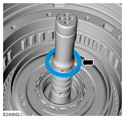
Install the new input shaft O-ring seals.
-
Install the input shaft in the E clutch and install the snap ring.
-
Install the (T7) thrust bearing onto the E clutch with the tab locators up. Snap the bearing into place.
-
NOTE:
Align the outer splines on the friction plates.
Install the input shaft and the E clutch into the No. 4 shell and sun gear.
-
Install the lower rear No. 3 ring gear snap ring.
-
Install the No. 3 ring gear and the snap ring. Align the snap ring gap 180° from the bottom snap ring gap.
-
Install the (T6) thrust bearing onto the E clutch with the tab locators down. Snap the bearing into place.
-
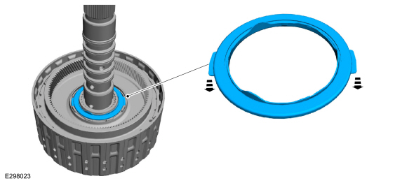
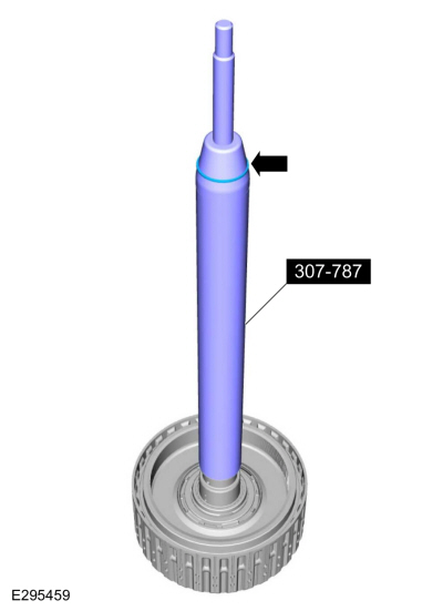
Install the special tool and adjust the special tool to
align the bottom edge of the tool with the top edge of the bottom
Teflon® seal groove.
Use Special Service Tool: 307-787
F8 Seal Installer/Sizer Input Shaft.
-
Install a new Teflon® seal on the special tool.
Use Special Service Tool: 307-787
F8 Seal Installer/Sizer Input Shaft.
-
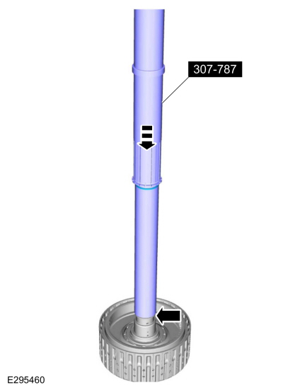
Using the top half of the special tool, slide the
Teflon® seal into the groove. Remove the special tools and repeat the
steps for the other 4 Teflon® seals.
Use Special Service Tool: 307-787
F8 Seal Installer/Sizer Input Shaft.
-
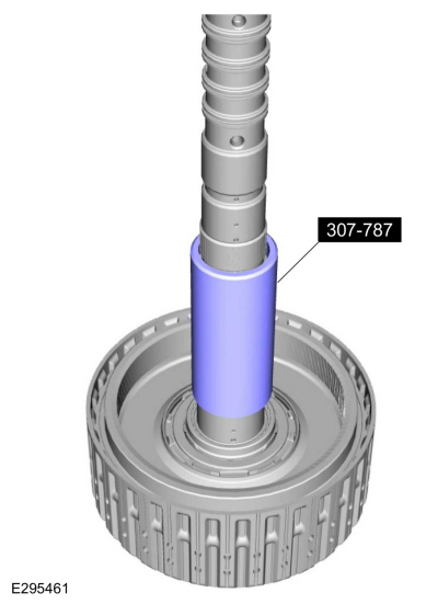
Install the special tool to size the 5 Teflon® seals.
Allow the special tool to stay on the input shaft for 5 minutes prior to
final assembly.
Use Special Service Tool: 307-787
F8 Seal Installer/Sizer Input Shaft.
-
Install the No. 1 sun gear in the No. 1 planetary carrier.
-
Install the No. 2 sun gear.
-
Install the No. 2 planetary carrier.
-
Install the (T5) bearing.
-
Remove Special Service Tool: 307-786
F7 Seal Installer/Sizer Input Shaft.
-
Install the No. 3 sun gear shaft into the CDF clutch assembly.
-
Position the CDF clutch assembly on 2 blocks of wood.
Use the General Equipment: Wooden Block
-
Rotate the No. 3 sun gear shaft back and forth to install.
-
While holding the sun gear No. 3 shaft, flip the CDF
clutch assembly over and install it on to the No. 2 planetary carrier.
-
Install the No. 3 planetary carrier.
-
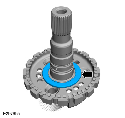
Install the No. 3 sun gear.
-
NOTE:
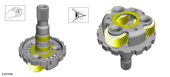
The No. 3 sun gear shaft splines will be flush with the No. 3 sun gear splines when correctly installed.
Check the No. 3 sun gear shaft for correct installation.
-
Remove Special Service Tool: 307-787
F8 Seal Installer/Sizer Input Shaft.
-
Install the E clutch and input shaft assembly.
-
Install the (T8) thrust bearing.
-
-
NOTE:
Some early build transmissions are not equipped with laser applied ink marks.
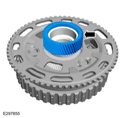
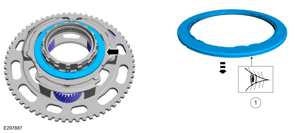
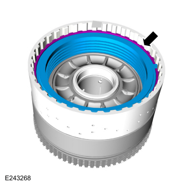
If the No. 4 ring gear was removed, inspect the ring
gear and the clutch and planetary container cylinder for laser applied
ink marks.
-
NOTICE:
If ink marks are present the marks must be aligned or a transmission vibration can occur.
If ink marks are present align the marks and install
the No. 4 ring gear on the clutch and planetary container cylinder.
-
Install the No. 4 ring gear snap ring.
.jpg) |
|
-
-
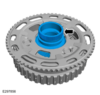
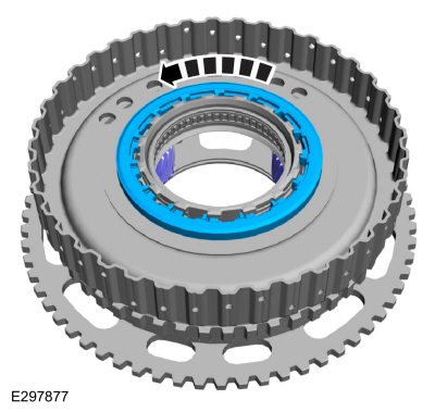
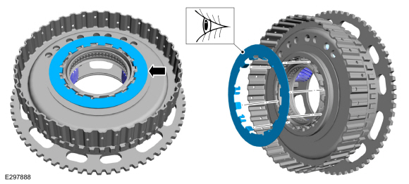
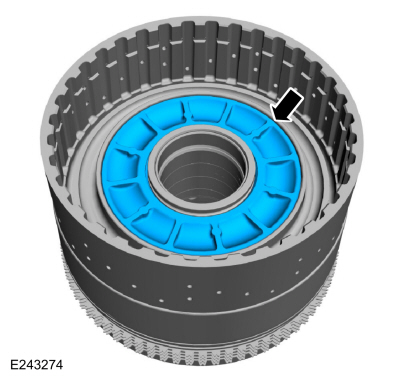
NOTE:
Some early build transmissions are not equipped with laser applied ink marks.
Inspect the No. 1 planetary carrier and the clutch
and planetary container cylinder for laser applied ink marks.
-
NOTICE:
If ink marks are present the marks must be aligned or a transmission vibration can occur.
If ink marks are present align the marks and install
the clutch and planetary container cylinder onto the No. 1 planetary
carrier and install the snap ring. Make sure the snap ring is seated.
-
Install the No. 1 planetary carrier snap ring. Make sure the snap ring is seated.
-
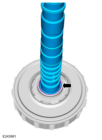
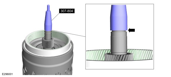
Install the special tool to the top edge of the Teflon® seal groove.
Use Special Service Tool: 307-804
F9 Seal Guide, Installer & Sizer.
-
Install a new Teflon® seal on the special tool.
Use Special Service Tool: 307-804
F9 Seal Guide, Installer & Sizer.
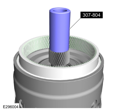
-
Using the top half of the special tool, slide the Teflon® seal into the groove.
Use Special Service Tool: 307-804
F9 Seal Guide, Installer & Sizer.
-
Using the special tool, size the Teflon® seal.
Use Special Service Tool: 307-804
F9 Seal Guide, Installer & Sizer.
-
Install the special tool and adjust the special tool to
align the bottom edge of the tool with the top edge of the bottom
Teflon® seal groove.
Use Special Service Tool: 307-796
F2 Seal Guide, Installer & Sizer.
-
Install a new Teflon® seal on the special tool.
Use Special Service Tool: 307-796
F2 Seal Guide, Installer & Sizer.
-
Using the top half of the special tool, slide the
Teflon® seal into the groove. Remove the special tools and repeat the
steps for the other 4 Teflon® seals.
Use Special Service Tool: 307-796
F2 Seal Guide, Installer & Sizer.
-
Install the special tool to size the 5 Teflon® seals.
Use Special Service Tool: 307-796
F2 Seal Guide, Installer & Sizer.
-
Install the TR sensor detent spring and loosely install the bolt.
-
Using the special tool install the new manual shaft seal in the transmission case.
Use Special Service Tool: 307-549
Installer, Shift Shaft Fluid Seal.
-
Slide the manual shaft into the TR sensor.
-
Using the dimpled end of the special tool, install the new manual shaft-to-TR sensor roll pin flush with the shaft.
-
New roll pin
-
Dimpled end of special tool
Use Special Service Tool: 307-783
Installer, Roll Pin.
Use the General Equipment: Rubber Mallet
-
Slide the end of the park return spring onto the transmission case.
-
-
Align the detent spring in the center of the TR sensor.
-
Torque:
97 lb.in (11 Nm)
-
NOTE:
A audible click should be heard when the (T10) thrust bearing is correctly installed.
Install the (T10) thrust bearing on the output shaft.
-
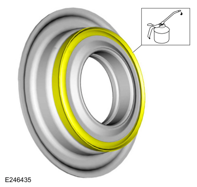
Install new seals on the output shaft.
-
Rotate the manual shaft to the park override position.
-
Install the output shaft and planetary carrier assembly No. 4.
-
Install the (T9) thrust bearing.
-
Lubricate the output shaft bushing with petroleum jelly.
-
Remove Special Service Tool: 307-796
F2 Seal Guide, Installer & Sizer.
-
Remove Special Service Tool: 307-804
F9 Seal Guide, Installer & Sizer.
-
Using the special tools and a floor crane, install the clutch and planetary assembly.
Use Special Service Tool: 307-651
Bracket, Pump Remover/Installer.
, 307-651-02
Lift fixture adapter for 307-651.
-
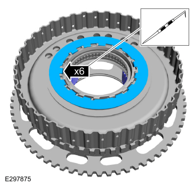
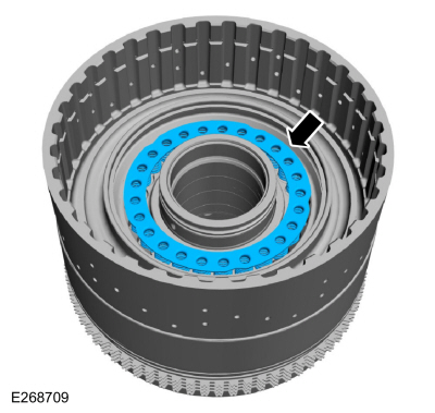
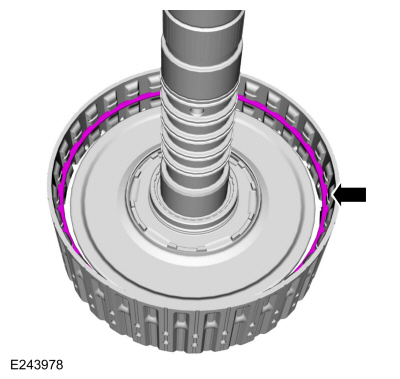
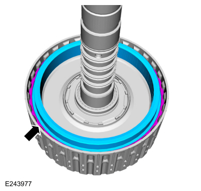
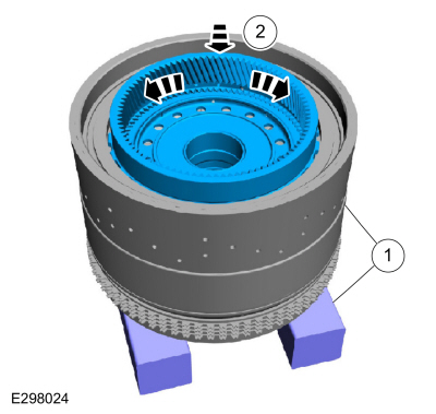
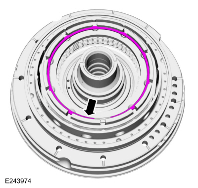
Using the special tool, remove the B clutch snap ring.
-
NOTE:
The B clutch snap ring ends are positioned in
the opening of the B clutch pressure plate with a raised notch.
Note the position of the B clutch snap ring ends for assembly.
-
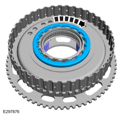
Using the special tools and a press, compress the B clutch assembly.
Use Special Service Tool: 307-741
Spring Compressor, F Clutch.
Use the General Equipment: Hydraulic Press
-
Remove the B clutch snap ring.
-
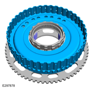
NOTICE:
Remove the One-Way Clutch (OWC) and B clutch
assembly gently, as the One-Way Clutch (OWC) rollers and springs could
become dislodged.
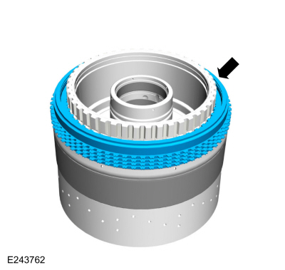
Gently remove the One-Way Clutch (OWC) and B clutch assembly.
-
NOTICE:
If replacing B clutch separating springs, all
separating springs must be replaced as a matching set or damage can
occur.
Remove the B clutch assembly from the One-Way Clutch
(OWC). Inspect the clutch plates for excessive wear or damage. If the
clutch plates are excessively worn or damaged replace as necessary. If
the clutch plates are not excessively worn or damaged, they can be
reused.
-
Remove the B clutch apply plate and the one remaining B clutch separating spring.
-
B clutch separating spring
-
B clutch apply plate
-
-
Use compressed air into the oil passage hole.
-
Remove and discard the B clutch piston.
-
-
Using the special tools and a press, compress the A clutch piston return spring.
Use Special Service Tool: 307-741
Spring Compressor, F Clutch.
, 307-785
Clutch spring compressor.
Use the General Equipment: Hydraulic Press
-
Remove the A clutch piston return spring snap ring.
-
Remove the A clutch piston return spring.
-
Use compressed air into the oil passage hole and remove the A clutch piston.
-
Remove and discard the A clutch piston outer seal and the A clutch piston inner seal.
-
Remove and discard the front support-to-case seal.
-
-
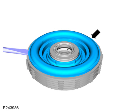
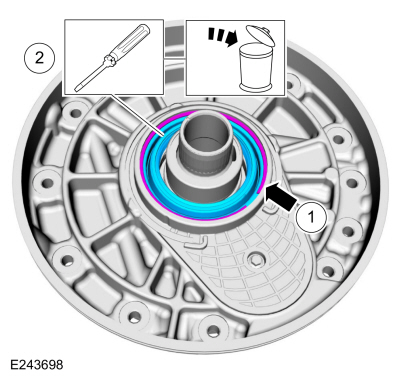
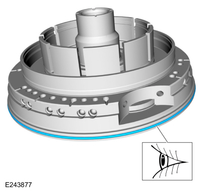
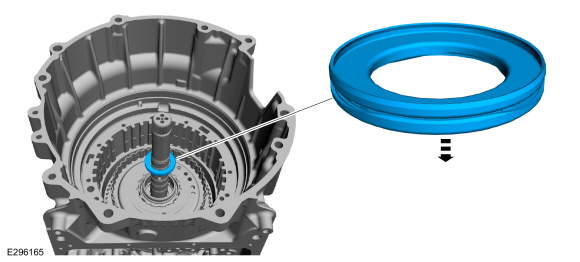
Remove the torque converter hub seal snap ring.
-
NOTE:
When removing the torque converter hub seal use
care not to scratch the front support cover sealing surface.
Remove and discard the torque converter hub seal.
-
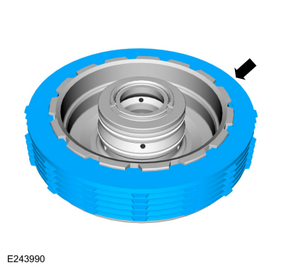
Remove the front support cover bolt and the front support cover snap ring.
-
-
NOTICE:
Do not pry on the transmission fluid pump drive
gear to remove the front support cover or damage to the transmission
fluid pump drive gear can occur.
-
Push up on the back of the front support cover and remove the front support cover from the front support.
-
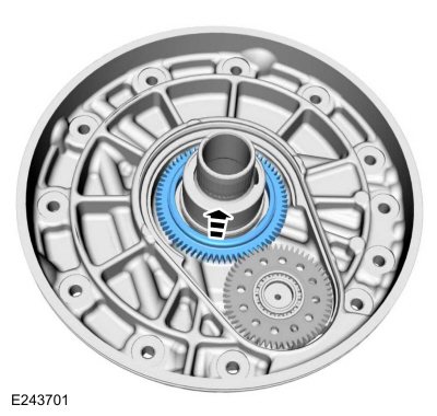
Remove the transmission fluid pump drive gear.
-
-
Inspect the transmission fluid pump idler gear for damage.
-
Make sure the transmission fluid pump idler gear bearing spins freely and has no excessive end play.
-
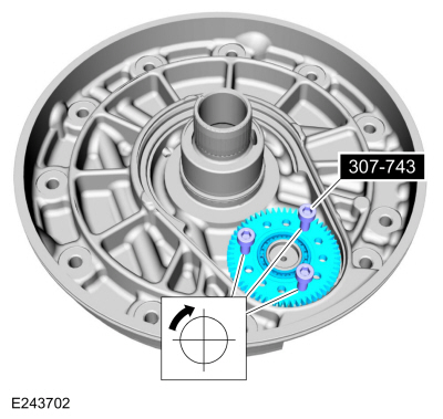
NOTE:
Tighten the special tools evenly to remove the transmission fluid pump idler gear.
If necessary, use the special tools, to remove the transmission fluid pump idler gear and bearing.
Use Special Service Tool: 307-743
Remover, Pump Drive Gear.
-
Using a press, to remove and discard the transmission fluid pump idler gear bearing.
Use the General Equipment: Hydraulic Press
-
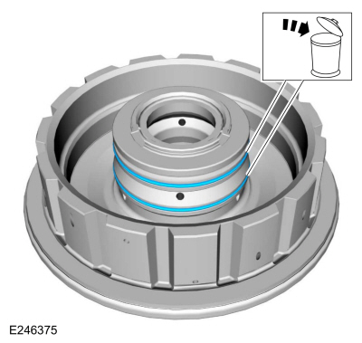
Remove and discard the stator support seal.
-
Clean and inspect the components for damage or excessive wear, replace as necessary.
-
One-Way Clutch (OWC) inner race
-
One-Way Clutch (OWC) rollers
-
Gear splines
-
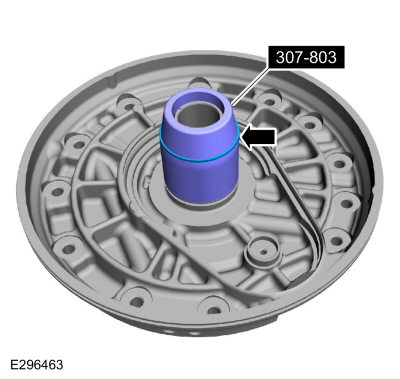
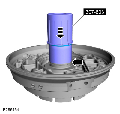
Install the special tool.
Use Special Service Tool: 307-803
F1 Seal Guide, Installer & Sizer.
-
Install a new Teflon® seal on the special tool.
Use Special Service Tool: 307-803
F1 Seal Guide, Installer & Sizer.
-
Using the top half of the special tool, slide the Teflon® seal into the groove.
Use Special Service Tool: 307-803
F1 Seal Guide, Installer & Sizer.
-
Install the special tool to size the Teflon® seal.
Use Special Service Tool: 307-803
F1 Seal Guide, Installer & Sizer.
-
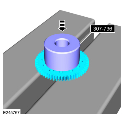
If removed, using the special tool and a press, install the new transmission fluid pump idler gear bearing.
Use Special Service Tool: 307-736
Installer, Pump Drive Gear Bearing.
Use the General Equipment: Hydraulic Press
-
-
Position the special tool on the front support.
Use Special Service Tool: 307-737
Press Tool, Oil Pump Drive Idler Gear.
-
NOTE:
Install the transmission fluid pump idler gear with the grooved side up.
-
Using the special tools and a press, install the transmission fluid pump idler gear and bearing.
Use the General Equipment: Hydraulic Press
-
Install the transmission fluid pump drive gear with the flat side down.
-
Install the front support cover by pressing down evenly by hand.
-
NOTE:
The front support cover snap ring ends are spaced evenly in the cover alignment features.
Install the front support cover bolt and the front support cover snap ring.
Torque:
62 lb.in (7 Nm)
-
Remove Special Service Tool: 307-803
F1 Seal Guide, Installer & Sizer.
-
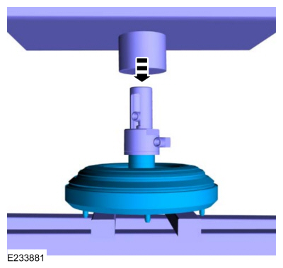
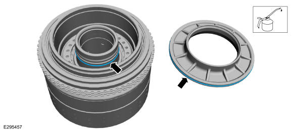
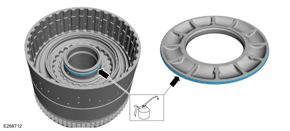
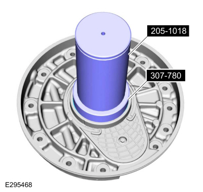
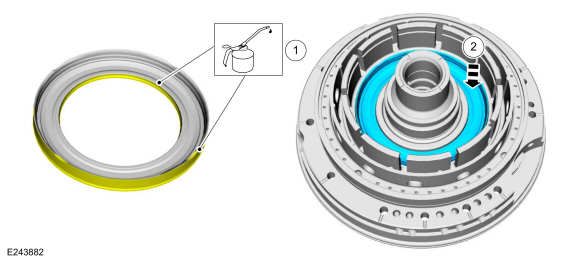
Install the new torque converter hub seal on the special tools.
Use Special Service Tool: 205-1018
Installation Tube.
, 307-780
Converter Seal installer.
-
Using the special tools, install the new torque converter hub seal.
Use Special Service Tool: 205-1018
Installation Tube.
, 307-780
Converter Seal installer.
-
Install the torque converter hub seal snap ring.
-
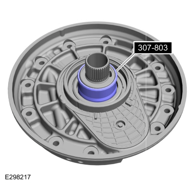
Install the special tool.
Use Special Service Tool: 307-803
F1 Seal Guide, Installer & Sizer.
-
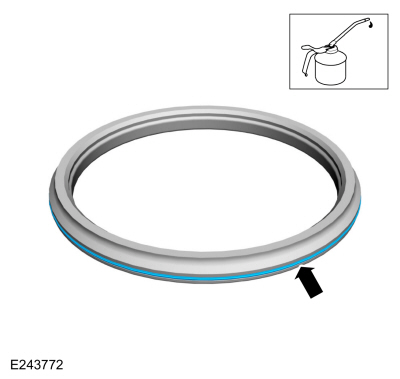
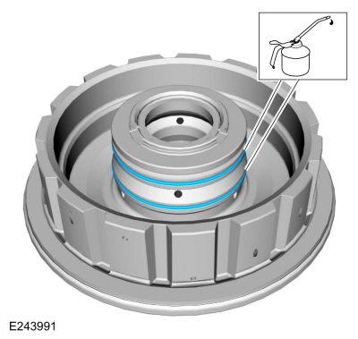
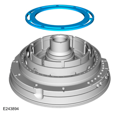
Install the new front support-to-case seal with the seal color visible from the outside.
-
Install the new A clutch piston outer seal and the new A
clutch piston inner seal. Lubricate the A clutch piston seals with
petroleum jelly.
-
Install the A clutch piston by pushing down on the piston until an audible click is heard.
-
Install the A clutch piston return spring with the retaining tabs facing upward.
-
-
Using the special tools and a press, compress the A clutch piston return spring.
Use Special Service Tool: 307-741
Spring Compressor, F Clutch.
, 307-785
Clutch spring compressor.
Use the General Equipment: Hydraulic Press
-
NOTE:
Be sure snap ring ends are not located on the A clutch piston return spring retaining tabs.
Install the A clutch piston return spring snap ring ends in the center of the return spring retaining tabs.
-
-
Lubricate the B clutch piston seals with petroleum jelly.
-
Install the new B clutch piston.
-
Install the B clutch apply plate.
-
NOTE:
The B clutch separating springs are not installed when measuring the B clutch clearance.
Temporarily install the B clutch friction plates, B
clutch steel plates and the B clutch pressure plate to measure the B
clutch clearance.
-
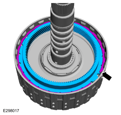
Install the B clutch snap ring with the grooved side down.
-
B clutch snap ring grooved side
-
Assemble the special tools and position the front support assembly on the special tool.
Use Special Service Tool: 307-662
Gauge, Clutch Pack Endplay.
, 307-003
(T57L-500-B)
Holding Fixture, Transmission.
-
Using the special tool, measure the B clutch clearance.
Position the plunger so it rests on the top surface of the pressure
plate. Gently push down on the pressure plate to zero the dial
indicator. Pull up on the pressure plate and measure and record the
clutch clearance in 3 different places. Average the 3 recorded clutch
clearance measurements and compare the measurement to the clutch
clearance chart in specifications to determine the correct size snap
ring. Install the correct B clutch snap ring.
Use Special Service Tool: 100-002
(TOOL-4201-C)
Holding Fixture with Dial Indicator Gauge.
-
Remove the B clutch snap ring.
-
Remove the B clutch assembly.
-
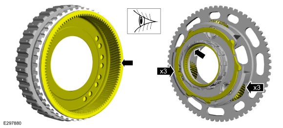
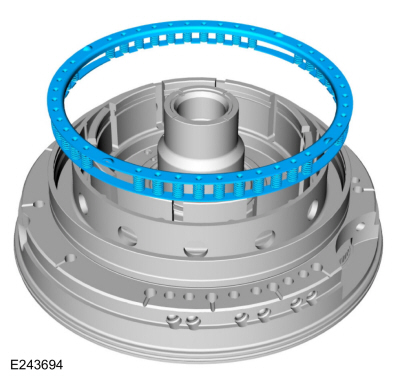
Verify that all the One-Way Clutch (OWC) rollers and springs are seated.
-
Springs
-
Rollers
-
NOTE:
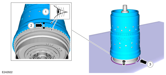
The One-Way Clutch (OWC) hub should rotate counter-clockwise freely when installed correctly.
-
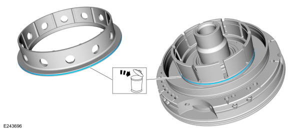
Position the special tool on the front support.
Use Special Service Tool: 307-784
One way clutch alignment tool.
-
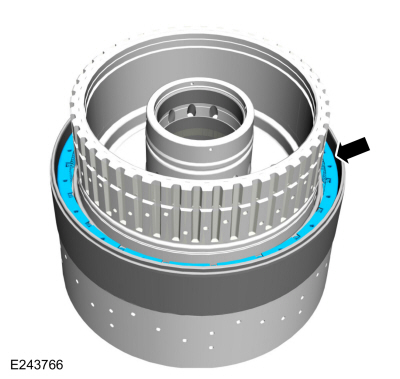
With a counter-clockwise rotation gently install the One-Way Clutch (OWC) onto the front support.
-
NOTICE:
If replacing B clutch separating springs, all
separating springs must be replaced as a matching set or damage can
occur.
NOTE:
Clutch plate quantity is model dependant based on engine displacement.
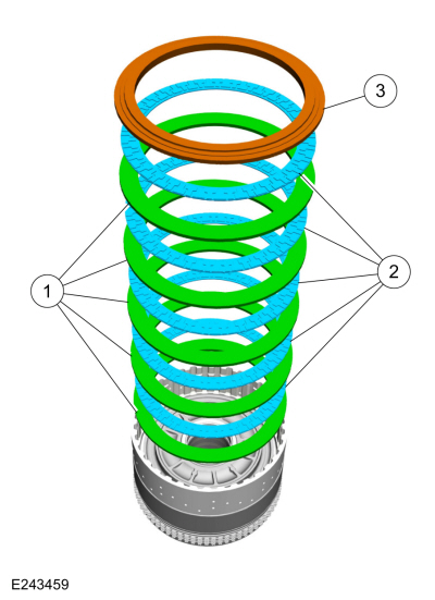
Soak the B clutch plates in clean transmission fluid.
With the B clutch apply plate installed, correctly install the B clutch
plates and springs.
-
B clutch friction plates
Material: Motorcraft® MERCON® ULV Automatic Transmission Fluid
/ XT-12-QULV
(WSS-M2C949-A, )
(MERCON® ULV)
-
B clutch separating springs
-
B clutch steel plates
-
B clutch pressure plate
-
NOTICE:
Be sure to align the top B clutch friction to the One-Way Clutch (OWC) hub or damage can occur.
Use the special tools to compress the B clutch assembly.
Use Special Service Tool: 307-741
Spring Compressor, F Clutch.
Use the General Equipment: Hydraulic Press
-
Install the B clutch snap ring in the correct location with the grooved side down.
-
B clutch snap ring grooved side
-
Install the (T3) thrust bearing.
-
Install the special tool.
Use Special Service Tool: 307-790
Endplay Check Gauge.
-
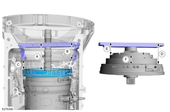
NOTE:
The special tool height 0.50 in (12.7 mm) must be
subtracted from the measurement to get the correct measurement A height.
Using the special tools and a depth gauge, measure the
distance from the top of the special tool to the top of the (T3) thrust
bearing special tool in 2 different places. Average the measurements and
subtract 0.50 in (12.7 mm). Record this as measurement A.
-
Measure it
-
Subtract it
Use Special Service Tool: 307-661
Gauge, End Play.
, 307-661-01
Spacers/Plate, Clearance Gage.
-
Using the special tool and a depth gauge, measure the
distance from the top of the special tool to the transmission deck
mating surface in 2 different places. Average the measurements. Record
this measurement as measurement B.
Use Special Service Tool: 307-661
Gauge, End Play.
-
Using the special tool and a depth gauge, measure the
distance from the top of the special tool to (T3) thrust bearing surface
in 2 different places. Average the measurements. Record this as
measurement C.
Use Special Service Tool: 307-661
Gauge, End Play.
-
NOTE:
Recorded measurement A compensates for the differences in height of the special tool.
Calculate the correct shim thickness. Subtract
measurement C from measurement B and record this as measurement D.
Subtract measurement D from measurement A to get the clearance between
the front support and the (T3) thrust bearing. Using the Selective Fit
Shim Charts in specifications, select the correct shim.
-
Install the selective shim.
-
NOTE:
The A clutch separating springs are not installed when measuring the A clutch clearance.
Temporarily install the A clutch into the transmission out of order to measure the A clutch clearance.
-
Install the pressure plate.
-
Install the friction plates.
-
Install the steel plates.
-
Install the wave spring.
-
Install the apply plate.
-
Using the special tools and a depth gauge, measure the
distance from the top of the special tool to the top of the A clutch
apply plate in 2 different places. Average the measurements. Record this
as measurement A.
Use Special Service Tool: 307-661
Gauge, End Play.
, 307-661-01
Spacers/Plate, Clearance Gage.
-
Using the special tools and a depth gauge, measure the
distance from the top of the special tool to the front support mating
surface in 2 different places. Average the measurements. Record this as
measurement B.
Use Special Service Tool: 307-661
Gauge, End Play.
, 307-661-01
Spacers/Plate, Clearance Gage.
-
Using the special tool and a depth gauge, measure the
distance from the top of the special tool to the transmission deck
mating surface in 2 different places. Average the measurements. Record
this as measurement D.
Use Special Service Tool: 307-661
Gauge, End Play.
-
Using the special tool and a depth gauge, measure the
distance from the top of the special tool to the A clutch piston surface
in 2 different places. Average the measurements. Record this as
measurement E.
Use Special Service Tool: 307-661
Gauge, End Play.
-
Subtract measurement B from measurement A and record
this as measurement C. Subtract measurement E from measurement D and
record this as measurement F. Subtract measurement F from measurement C
to get the A clutch clearance. Compare the A clutch clearance to the
clutch specifications chart. If the A clutch clearance is not with in
the specification range select the correct A clutch apply plate.
-
NOTICE:
If replacing A clutch separating springs, all
separating springs must be replaced as a matching set or damage can
occur.
NOTE:
Clutch plate quantity is model dependant based on engine displacement.
Soak the A clutch plates in clean transmission fluid. Install the A clutch assembly.
-
Pressure plate
-
Friction plates
Material: Motorcraft® MERCON® ULV Automatic Transmission Fluid
/ XT-12-QULV
(WSS-M2C949-A, )
(MERCON® ULV)
-
Separator springs
-
Steel plates
-
Apply plate (select fit)
-
Wave spring
-
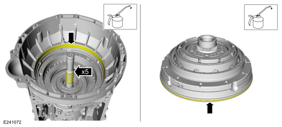
Lubricate the transmission case-to-front support sealing
surface, the Teflon seals and the front support O-ring with petroleum
jelly.
-
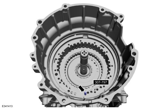
Install the special tool in the location shown.
Use Special Service Tool: 307-797
Installer, Alignment Studs (3) & Alignment Pin (All 10R).
-
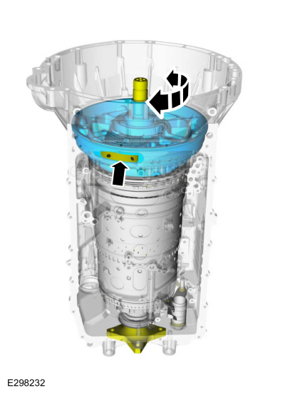
Install the front support into the transmission case.
Align the pump gear to the pump drive gear pocket area. Rotate the input
shaft to align the one-way clutch splines with the No. 1 sun gear.
-
-
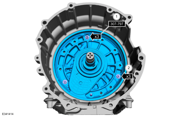
Install the special tool studs, washers and nuts in the location shown.
Use Special Service Tool: 307-797
Installer, Alignment Studs (3) & Alignment Pin (All 10R).
-
Tighten the special tool nuts evenly to seat the front support assembly to the transmission case.
-
NOTE:
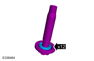
New bolts are produced with the washers installed.
If the bolts are being reused the new washers must be installed.
If necessary, install the new front support assembly bolt washers.
-
-
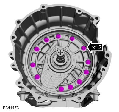
With the special tools installed, hand tight the front support bolts in a crisscross pattern.
-
Remove the special tools and install the front support bolts hand tight.
-
Tighten the front support bolts in a crisscross pattern.
Torque:
26 lb.ft (35 Nm)
-
Remove Special Service Tool: 307-803
F1 Seal Guide, Installer & Sizer.
-
Using the special tool, install the torque converter.
Use Special Service Tool: 307-091
Handle, Torque Converter.
-
Install the special tool to hold the torque converter.
Use Special Service Tool: 307-346
(T97T-7902-A)
Retainer, Torque Converter.
-
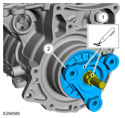
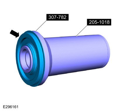
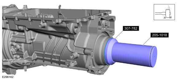
Position a new output shaft seal on the special tools.
Use Special Service Tool: 205-1018
Installation Tube.
, 307-782
Installer, Output Shaft Seal.
-
Using the special tools, install the new output shaft seal.
Use Special Service Tool: 205-1018
Installation Tube.
, 307-782
Installer, Output Shaft Seal.
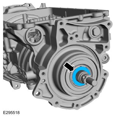
Rear Wheel Drive (RWD) vehicles
-
Install the anti-ting washer.
-
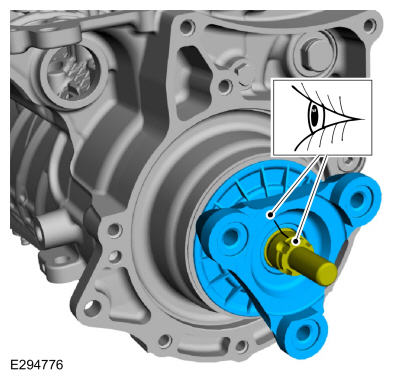
NOTE:
If the output shaft or output shaft flange are replaced with new parts, align laser applied ink marks.
Align the index marks made during removal.
-
Install the new output shaft flange retaining nut.
Torque:
59 lb.ft (80 Nm)
-
After installing the new output shaft flange retaining nut, stake the slots to prevent it from coming loose.
Use the General Equipment: Punch
All vehicles
-
Install the wiring harness. Lubricate the O-ring seals
with petroleum jelly. Align the tab on the electrical connector with the
indention in the transmission case and install the main electrical
connector in the transmission case. Align the wiring harness and install
the bolts.
-
Torque:
97 lb.in (11 Nm)
-
Torque:
106 lb.in (12 Nm)
-
Support the opposite side of the TR sensor and connect the electrical connector.
-
Install the speed sensors.
-
Intermediate Speed Sensor A (ISSA)
-
TSS sensor
-
Intermediate Speed Sensor B (ISSB)
-
OSS sensor
-
Connect and lock the speed sensors.
-
Intermediate Speed Sensor A (ISSA)
-
TSS sensor
-
Intermediate Speed Sensor B (ISSB)
-
OSS sensor
-
If removed, install the transmission fluid pump driven gear inner cover and the bolts.
Torque:
115 lb.in (13 Nm)
-
-
If removed, install the transmission fluid pump driven gear and the retaining ring.
-
Install the transmission fluid pump driven gear outer cover.
-
Install the transmission fluid pump and the bolts.
Torque:
71 lb.in (8 Nm)
-
Rotate the manual shaft to the park override position.
-
NOTICE:
Only install 68 mm length bolts or the transmission
clutch and planetary container can be damaged and result in transmission
failure.
Loosely install the main control valve body.
-
NOTE:
Be sure the main control-to-case seal is attached to the main control.
-
Align the guide pins on the main control valve body with the alignment holes in the transmission case.
-
Align the TR sensor with the park pawl lock valve.
-
Loosely install the 68 mm length main control-to-transmission case bolts.
-
Tighten the bolts in the sequence shown.
Torque:
89 lb.in (10 Nm)
-
Connect the main control electrical connector.
-
Install the filter seal in the pump.
-
NOTICE:
If the bolts are installed in the wrong locations, transmission damage will occur.
NOTE:
The transmission fluid filter may be reused if no excessive contamination is indicated.
Install the filter and the bolts in the correct locations.
-
Short bolt 20 mm
-
Long bolt 71 mm
-
Torque:
93 lb.in (10.5 Nm)
Auto-Start-Stop vehicles
-
NOTE:
If the transmission fluid was contaminated from a
catastrophic failure, replace the transmission fluid auxiliary pump.
Install the transmission fluid auxiliary pump and loosely install the bolts.
-
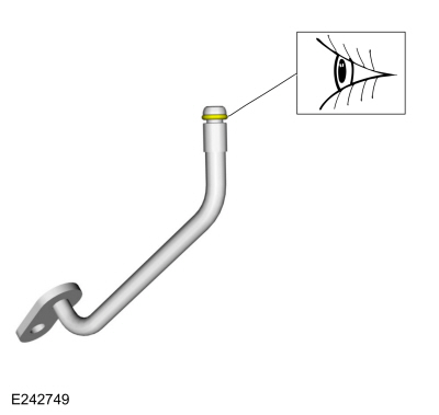
Install the new transmission fluid auxiliary pump tube seal.
-
Inspect the transmission fluid auxiliary pump tube O-ring.
-
Install the transmission fluid auxiliary pump tube and loosely install the bolt.
-
-
Transmission fluid auxiliary pump bolts
Torque:
97 lb.in (11 Nm)
-
Transmission fluid auxiliary pump tube bolt
Torque:
106 lb.in (12 Nm)
-
Connect the transmission fluid auxiliary pump electrical connector.
All vehicles
-
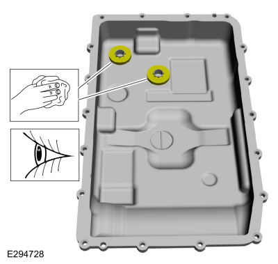
Clean and inspect the magnets and the retainers.
-
NOTE:
The transmission fluid pan gasket can be reused if not damaged.
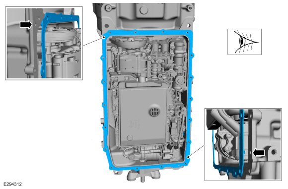
Align the tabs in the noted location and install the transmission fluid pan gasket.
-
NOTE:
Install the studbolts and bolts in the correct locations noted during removal.
Install the transmission fluid pan and loosely install the studbolts and bolts.
-
Tighten the studbolts in a crisscross pattern.
Torque:
106 lb.in (12 Nm)
-
Tighten the bolts in a crisscross pattern.
Torque:
89 lb.in (10 Nm)
-
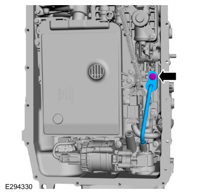
Loosely install the transmission fluid level indicator and plug assembly.
-
Install the park override lever and the nut.
Torque:
106 lb.in (12 Nm)
Special Tool(s) /
General Equipment
307-299Alignment Pins, Valve BodyTKIT-1994-LMH/MH2TKIT-1994-FTKIT-1994-FLM/FM
Materials
Name
Specification
Motorcraft® MERCON® ULV Automatic Transmission FluidXT-12-QULV
WSS-M2C949-A, MERCON® ULV
For solenoid and valve identification...
Special Tool(s) /
General Equipment
204-594Forcing screw
307-549Installer, Shift Shaft Fluid SealTKIT-2005D1-F1
307-648Remover/Installer, Rear BearingTKIT-2009C-FTKIT-2009C-ROW
307-745Installer, Park Sleeve Roll Pin
307-781Needle bearing remover/Installer
307-788Installer, sleeve
307-789Installer, sleeve
NOTE:
This step is only necessary if the transmission case is
being replaced...
Other information:
Maintenance is an investment that pays
dividends in the form of improved reliability,
durability and resale value. To maintain the
proper performance of your vehicle and its
emission control systems, make sure you
have scheduled maintenance performed at
the designated intervals...
Special Tool(s) /
General Equipment
Plastic Scraper
Materials
Name
Specification
Motorcraft® High Performance Engine RTV SiliconeTA-357
WSE-M4G323-A6
Motorcraft® Silicone Gasket RemoverZC-30-A
-
Motorcraft® Metal Surface Prep WipesZC-31-B
-
Motorcraft® Metal Brake Parts CleanerPM-4-A, PM-4-B
-
Removal
NOTICE:
During engine repair procedures, cleanliness is extremely
important...
.jpg)
.jpg)
.jpg)
.jpg)
.jpg)
.jpg)
.jpg)
.jpg)
.jpg)
.jpg)
.jpg)
.jpg)
.jpg)
.jpg)
.jpg)
.jpg)
.jpg)
.jpg)
.jpg)
.jpg)
.jpg)
.jpg)
.jpg)


.jpg)
.jpg)
.jpg)
.jpg)
.jpg)
.jpg)
.jpg)
.jpg)
.jpg)
.jpg)
.jpg)
.jpg)
.jpg)
.jpg)
.jpg)

.jpg)
.jpg)
.jpg)
.jpg)
.jpg)
.jpg)
.jpg)
.jpg)
.jpg)
.jpg)
.jpg)
.jpg)
.jpg)
.jpg)
.jpg)
.jpg)
.jpg)
.jpg)
.jpg)
.jpg)
.jpg)
.jpg)
.jpg)
.jpg)
.jpg)
.jpg)
.jpg)
.jpg)
.jpg)
.jpg)
.jpg)
.jpg)
.jpg)
.jpg)
.jpg)
.jpg)
.jpg)

.jpg)
.jpg)
.jpg)
.jpg)
.jpg)
.jpg)
.jpg)
.jpg)
.jpg)
.jpg)
.jpg)
.jpg)
.jpg)
.jpg)
.jpg)
.jpg)
.jpg)
.jpg)
.jpg)
.jpg)
.jpg)
.jpg)
.jpg)
.jpg)
.jpg)

.jpg)
.jpg)
.jpg)
.jpg)
.jpg)
.jpg)
.jpg)
.jpg)
.jpg)
.jpg)
.jpg)
.jpg)
.jpg)
.jpg)
.jpg)
.jpg)
.jpg)
.jpg)
.jpg)
.jpg)
.jpg)
.jpg)
.jpg)
.jpg)
.jpg)
.jpg)
.jpg)
.jpg)
.jpg)
.jpg)
.jpg)
.jpg)
.jpg)
.jpg)
.jpg)
.jpg)
.jpg)
.jpg)
.jpg)
.jpg)
.jpg)
.jpg)
.jpg)
.jpg)
.jpg)
.jpg)
.jpg)
.jpg)
.jpg)
.jpg)
.jpg)
.jpg)
.jpg)
.jpg)
.jpg)
.jpg)
.jpg)
.jpg)
.jpg)
 Overhaul - Main Control Valve Body
 Assembly - Transmission Case