Lincoln Aviator: Front End Body Panels / Removal and Installation - Active Grille Shutter Actuator
Removal
NOTE: Removal steps in this procedure may contain installation details.
-
Remove the Radiator grille opening panel.
Refer to: Radiator Grille Opening Panel (501-02 Front End Body Panels, Removal and Installation).
Upper active grille shutter actuator
-
Remove the upper actuator spacer assembly.
.jpg) |
-
Disconnect the electrical connector and the bolt.
Torque: 44 lb.in (5 Nm)
.jpg) |
NOTE: The upper active grille shutter actuator is not interchangeable with the lower active grill shutter actuator. Do not attempt to replace one actuator with the other.
-
Pull and remove the upper active grille shutter actuator.
.jpg) |
Lower active grille shutter actuator
-
Remove the lower actuator spacer assembly.
.jpg) |
-
Disconnect the electrical connector and the bolt.
Torque: 44 lb.in (5 Nm)
.jpg) |
NOTE: The lower active grille shutter actuator is not interchangeable with the upper active grill shutter actuator. Do not attempt to replace one actuator with the other.
-
Pull and remove the lower active grille shutter actuator.
.jpg) |
Installation
-
To install, reverse the removal procedure.
 Diagnosis and Testing - Active Grille Shutter
Diagnostic Trouble Code (DTC) Chart
Diagnostics in this manual assume a certain skill level and knowledge of Ford-specific diagnostic practices. REFER to: Diagnostic Methods (100-00 General Information, Description and Operation)...
 Removal and Installation - Cowl Panel
Removal
NOTE:
Removal steps in this procedure may contain installation details.
Remove the wiper linkage assembly.
Refer to: Wiper Linkage Assembly (501-16 Wipers and Washers, Removal and Installation)...
Other information:
Lincoln Aviator 2020-2026 Service Manual: Description and Operation - Health and Safety Precautions
General Service Warnings Review carefully the information below before beginning any repair. Following these warnings is a list of specific system warnings that must be reviewed before beginning work on any listed system. WARNING: Vehicles equipped with an automatic transmission and a Telematics Control Unit (TCU) have remote start technology and may start the engine at any time...
Lincoln Aviator 2020-2026 Service Manual: General Procedures - Engine Cooling System Draining, Vacuum Filling and Bleeding
Special Tool(s) / General Equipment ROB75240Coolant/Battery Refractometer (Fahrenheit) Fluid Container Cooling System Vacuum Tester and Refiller Draining NOTICE: The coolant must be recovered in a suitable, clean container for reuse...
Categories
- Manuals Home
- Lincoln Aviator Owners Manual
- Lincoln Aviator Service Manual
- Body and Paint
- Drive Modes
- Disabling Auto-Start-Stop
- New on site
- Most important about car
Activating Intelligent Access
The intelligent access key must be within 3 ft (1 m) of the door or luggage compartment you intend to lock or unlock.
At a Door
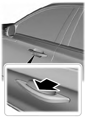
Electronic door handles are on each door. Gently depress the switch inside the exterior door handle to unlock and open the door. An unlock symbol illuminates on the door window trim indicating your vehicle is unlocked.

