Lincoln Aviator: Climate Control System - General Information / Removal and Installation - Air Conditioning (A/C) Compressor - 3.0L EcoBoost
Removal
NOTICE: If installing a new A/C compressor due to an internal failure of the old unit, carry out the following procedures to remove contamination from the A/C system. Failure to remove contamination from the A/C system, if present, will result in poor A/C performance and/or damage to the new A/C compressor and other components.
- If A/C flushing equipment is available, carry out flushing of the A/C system prior to installing a new A/C compressor.
- If A/C flushing equipment is not available, replace all contaminated components after a new A/C compressor has been installed.
- Install a new Thermostatic Expansion Valve (TXV) as directed by the A/C flushing.
- Install a new receiver drier element as directed by the A/C flushing.
NOTICE: During the removal of components, cap, tape or otherwise appropriately protect all openings to prevent the ingress of dirt or other contamination. Remove protective materials prior to installation.
NOTE: Installation of a new receiver drier element is not required when repairing the A/C system except when there is physical evidence of system contamination from a failed A/C compressor or damage to the receiver drier element.
NOTE: A new A/C compressor may come equipped with an A/C clutch disc and hub, A/C compressor pulley and A/C clutch field coil already installed. If these components are not pre-installed, it will be necessary to transfer these parts from the old A/C compressor to the new compressor prior to installation of the A/C compressor if suitable for reuse.
NOTE: Removal steps in this procedure may contain installation details.
-
Recover the refrigerant. Refer to the appropriate Recovery procedure in Group 412.
-
Remove the bolts and the suspension support bar.
Torque: 22 lb.ft (30 Nm)
.jpg) |
-
Remove the PCM.
Refer to: Powertrain Control Module (PCM) (303-14A Electronic Engine Controls - 3.0L EcoBoost/3.0L EcoBoost – Hybrid (BQ), Removal and Installation).
-
Disconnect the harness retainers. Remove the bolts and the PCM mounting bracket.
Torque: 55 lb.in (6.2 Nm)
.jpg) |
-
Remove the RH upper air cleaner outlet pipe.
Refer to: Air Cleaner Outlet Pipe RH (303-12 Intake Air Distribution and Filtering - 3.0L EcoBoost/3.0L EcoBoost – Hybrid (BQ), Removal and Installation).
-
Remove the RH
CAC intake pipe.
Refer to: Charge Air Cooler (CAC) Intake Pipe (303-12 Intake Air Distribution and Filtering - 3.0L EcoBoost/3.0L EcoBoost – Hybrid (BQ), Removal and Installation).
-
Remove the accessory drive belt.
Refer to: Accessory Drive Belt (303-05A Accessory Drive - 3.0L EcoBoost, Removal and Installation).
-
-
Detach the clips.
-
Remove the nut.
Torque: 25 lb.in (2.8 Nm)
-
Detach the clips.
.jpg) |
-
-
Disconnect the A/C wiring harness electrical connector.
-
Detach the wiring harness retainer.
-
Remove the lower bolt from the A/C compressor.
Torque: 18 lb.ft (25 Nm)
-
Disconnect the A/C wiring harness electrical connector.
.jpg) |
-
Remove the A/C compressor inlet and outlet line retainers and position aside lines.
-
Make sure to cover any open ports to prevent debris from entering the system.
Torque: 159 lb.in (18 Nm)
-
Make sure to cover any open ports to prevent debris from entering the system.
.jpg) |
-
-
Disconnect the A/C electrical connector.
-
Remove the bolts and the A/C compressor.
Torque: 18 lb.ft (25 Nm)
-
Disconnect the A/C electrical connector.
.jpg) |
Installation
-
To install, reverse the removal procedure.
-
NOTICE: Only use the specified material to lubricate the seals.
Install and lubricate new O-ring seals. Refer to the appropriate Specifications in Group 412.
-
Lubricate the refrigerant system with the correct amount
of clean PAG oil. Refer to the appropriate Refrigerant Oil Adding
procedure in Group 412.
 General Procedures - Refrigerant System Tests - 3.0L EcoBoost
Inspection
NOTE:
Procedure 1 — Ambient Temperature below 21 °C (70 °F).
NOTE:
Proper A/C system diagnosis on a vehicle’s
compressor is dependent on correct refrigerant system charge and tested
in ambient temperatures above 21°C (70°F)...
 Removal and Installation - Air Conditioning (A/C) Compressor Inlet Line - 3.0L EcoBoost
Removal
NOTICE:
During the removal of components, cap, tape or otherwise
appropriately protect all openings to prevent the ingress of dirt or
other contamination...
Other information:
Lincoln Aviator 2020-2025 Service Manual: Removal and Installation - Second Row Single Seat Armrest - Vehicles With: Second Row Captain Chairs
Removal NOTE: Removal steps in this procedure may contain installation details. Unzip the second row single seat armrest cover. Remove the second row single seat armrest. Invert the single seat armrest cover to access the armrest pivot bolt...
Lincoln Aviator 2020-2025 Service Manual: General Procedures - Finish Panel Repair
Repair NOTE: Mouldings located on the front and rear window frames may experience minor scratches from vehicle shipment or car wash racks. The imperfections may be repaired instead of replacing components by following the steps below. NOTE: Scratches deep enough to cause a thumb nail to catch cannot be repaired and the component must be replaced...
Categories
- Manuals Home
- Lincoln Aviator Owners Manual
- Lincoln Aviator Service Manual
- Activating Intelligent Access
- Changing the Front Wiper Blades - Vehicles With: Heated Wiper Blades
- USB Port and Power Point Locations
- New on site
- Most important about car
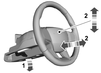
Adjusting the Steering Wheel - Vehicles With: Manual Adjustable Steering Column
WARNING: Do not adjust the steering wheel when your vehicle is moving.
Note: Make sure that you are sitting in the correct position.
Unlock the steering column. Adjust the steering wheel to the desired position.
