Lincoln Aviator: Engine - 3.0L EcoBoost / Removal and Installation - Engine Front Cover
Special Tool(s) /
General Equipment
.jpg) |
303-050
(T70P-6000)
Lifting Bracket, Engine |
.jpg) |
303-F070
Support Bar, Engine
TKIT-1999A-F/LT
TKIT-1999A-FM/FLM |
| Plastic Scraper |
| Hose Clamp Remover/Installer |
| Flat-Bladed Screwdriver |
Materials
| Name |
Specification |
Motorcraft® High Performance Engine RTV Silicone
TA-357 |
WSE-M4G323-A6
|
Motorcraft® Metal Brake Parts Cleaner
PM-4-A, PM-4-B |
-
|
Removal
NOTICE:
During engine repair procedures, cleanliness is extremely
important. Any foreign material, including any material created while
cleaning gasket surfaces, that enters the oil passages, coolant passages
or the oil pan, can cause engine failure.
LHD AWD/LHD RWD
-
With the vehicle in NEUTRAL, position it on a hoist.
Refer to: Jacking and Lifting (100-02 Jacking and Lifting, Description and Operation).
-
Release the fuel system pressure.
Refer to: Fuel System Pressure Release (310-00A Fuel System - General Information - 3.0L EcoBoost, General Procedures).
-
Disconnect the battery ground cable.
Refer to: Battery Disconnect and Connect (414-01 Battery, Mounting and Cables, General Procedures).
-
Drain the engine cooling system.
Refer to: Engine Cooling System Draining, Vacuum Filling and Bleeding (303-03A Engine Cooling - 3.0L EcoBoost, General Procedures).
-
Remove the following items:
-
Refer to: Oil Pan (303-01A Engine - 3.0L EcoBoost, Removal and Installation).
-
Refer to: Degas Bottle (303-03A Engine Cooling - 3.0L EcoBoost, Removal and Installation).
-
Refer to: Valve Cover RH (303-01A Engine - 3.0L EcoBoost, Removal and Installation).
-
Refer to: Valve Cover LH (303-01A Engine - 3.0L EcoBoost, Removal and Installation).
-
Refer to: Oil Cooler (303-01A Engine - 3.0L EcoBoost, Removal and Installation).
-
Release the clamps and disconnect the upper and lower radiator hoses.
-
Position the hoses aside.
-
Remove the following items:
-
Refer to: Accessory Drive Belt Tensioner (303-05A Accessory Drive - 3.0L EcoBoost, Removal and Installation).
-
NOTE:
It is not necessary to remove the
thermostat housing. The coolant pump and thermostat housing can be
removed as an assembly.
Refer to: Coolant Pump (303-03A Engine Cooling - 3.0L EcoBoost, Removal and Installation).
-
Refer to: Generator - 3.0L EcoBoost (414-02 Generator and Regulator, Removal and Installation).
-
Refer to: Crankshaft Front Seal (303-01A Engine - 3.0L EcoBoost, Removal and Installation).
LHD AWD
-
Remove the LH and RH front halfshafts.
Refer to: Halfshaft (205-04 Front Drive Halfshafts, Removal and Installation).
-
NOTE:
LH shown, RH similar.
Remove the bolts and the front suspension height sensors.
LHD AWD/LHD RWD
-
NOTE:
The original engine mount-to-engine bolts and
subframe bolts will be required to temporarily install the engine mount
and subframe. Do not discard these fasteners until instructed to in this
engine front cover procedure.
Remove the LH engine mount.
Refer to: Engine Mount LH (303-01A Engine - 3.0L EcoBoost, Removal and Installation).
LHD AWD
-
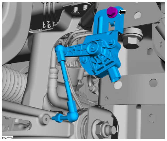
Disconnect the front axle disconnect actuator electrical connector and vent hose.
-
Remove the bolts and the front axle disconnect actuator.
-
Remove and discard the seal.
LHD AWD/LHD RWD
-
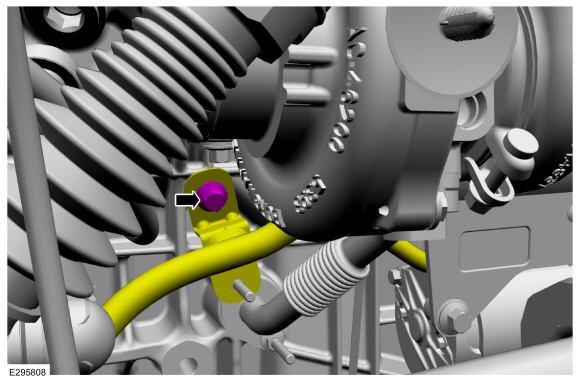
Remove the wire harness bracket bolt, then move out of the way.
-
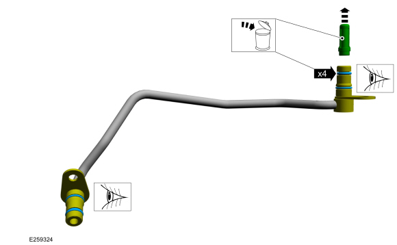
Remove the turbocharger oil return tube bolts, then remove the turbocharger oil return tube.
-
-
Remove and discard the turbocharger oil return tube O-ring seal.
-
Remove and discard the turbocharger oil return tube tube-to-engine block gasket.
-
Install the LH engine mount, the original bolts finger-tight and then tighten in sequence.
Torque:
46 lb.ft (63 Nm)
-
NOTE:
Make sure that the LH and RH engine mount studs are in the subframe when raised.
With the aid of an assistant, raise the front and rear jack stand evenly.
-
Install the original front subframe bolts finger tight.
-
Install the original middle subframe bolts finger tight.
-
Install the original rear subframe bolts finger tight.
-
Tighten the front subframe bolts.
Torque:
195 lb.ft (265 Nm)
-
Tighten the middle subframe bolts.
Torque:
195 lb.ft (265 Nm)
-
Tighten the rear subframe bolts.
Torque:
52 lb.ft (70 Nm)
-
Remove adjustable jack stands.
-
Remove Special Service Tool: 303-F070
Support Bar, Engine.
-
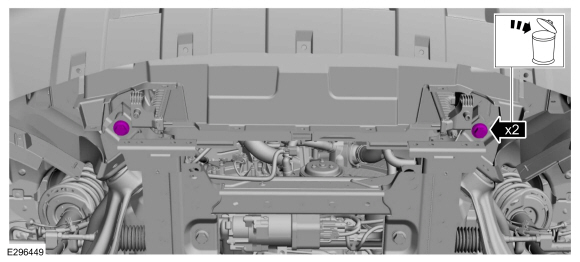
Remove the two M8 x 1.25 x 105 mm bolts, two washers, and the special tools.
Remove Special Service Tool: 303-050
(T70P-6000)
Lifting Bracket, Engine.
-
Remove the bolts and the heat shield.
-
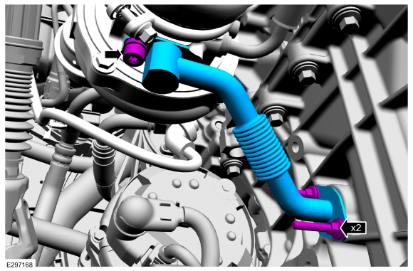
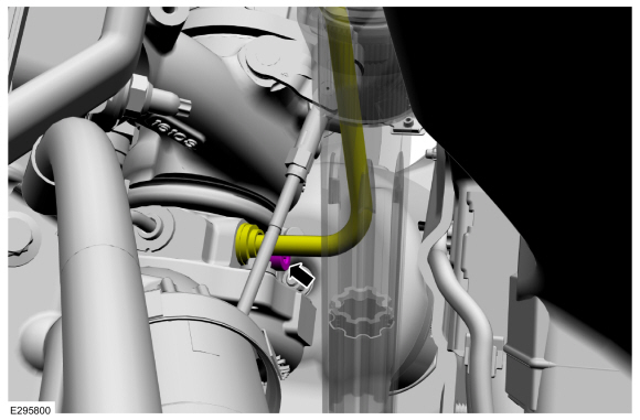
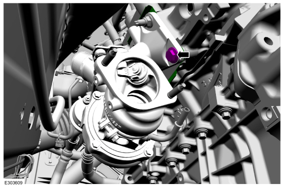
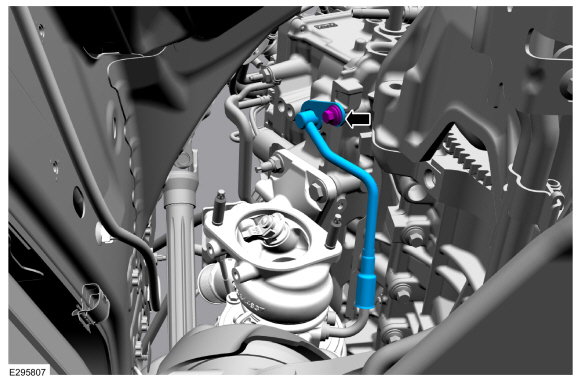
Remove the bolt, then disconnect the turbocharger coolant return tube from the turbocharger.
-
-
Remove and discard the turbocharger coolant return tube O-ring seal.
-
Remove the turbocharger oil supply tube bolt, then disconnect the turbocharger oil supply tube.
-
Disconnect the clamp and the turbocharger wastegate control hose.
Use the General Equipment: Hose Clamp Remover/Installer
-
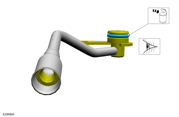
Remove the turbocharger coolant supply tube bolt, then remove the outer tube.
-
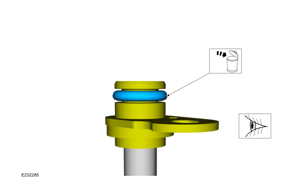
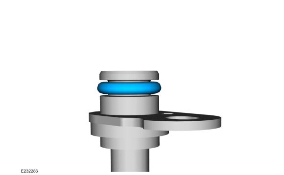
-
Remove and discard the turbocharger coolant
supply tube O-ring seal. Inspect the rubber gasket. Install new
components if needed.
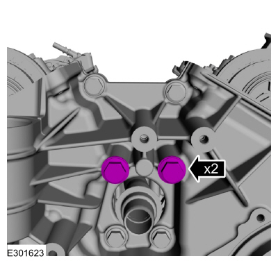
-
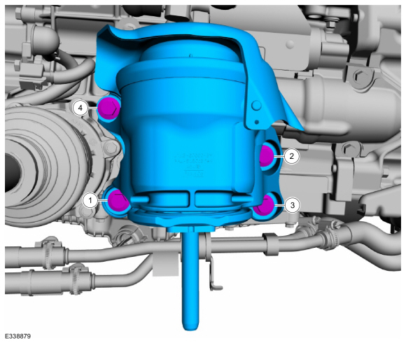
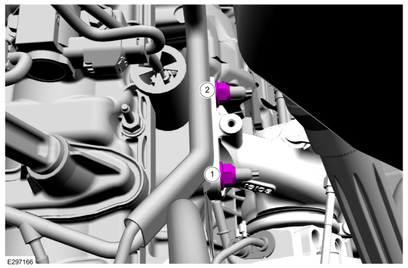
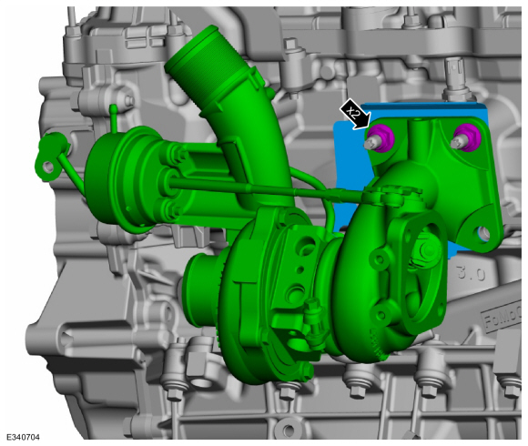
Remove the upper turbocharger nuts.
-
Remove the turbocharger studs.
-
Remove the turbocharger bolt, then remove the turbocharger and gasket. Discard the gasket.
-
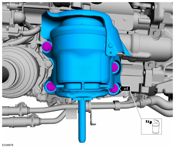
Remove the turbocharger oil supply tube bolt, then
disconnect the turbocharger oil supply tube from the turbocharger.
-
-
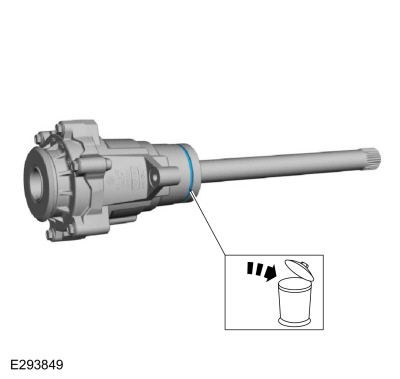
Remove and discard the turbocharger oil supply
tube O-ring seals and the turbocharger oil supply tube oil filter.
Install new components if needed.
-
-
Remove and discard the turbocharger coolant return tube O-ring seals.
-
Detach the wiring harness retainer.
-
Remove the bolt and idler pulley.
-
NOTE:
There are 5 different types of fasteners, note location of each fastener for assembly.
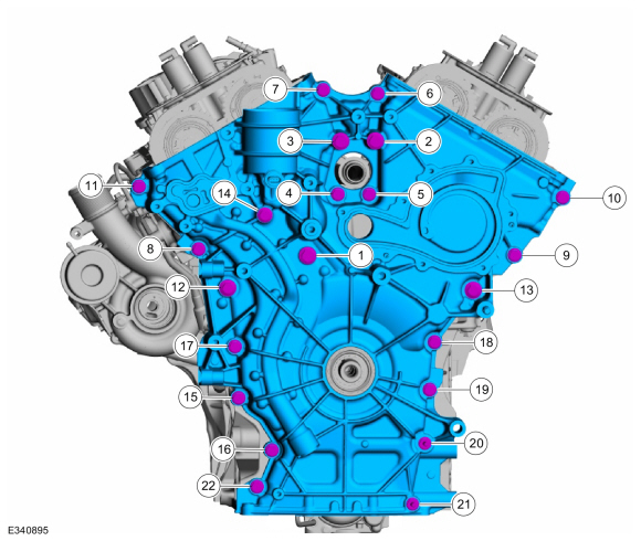
Remove the engine front cover fasteners.
-
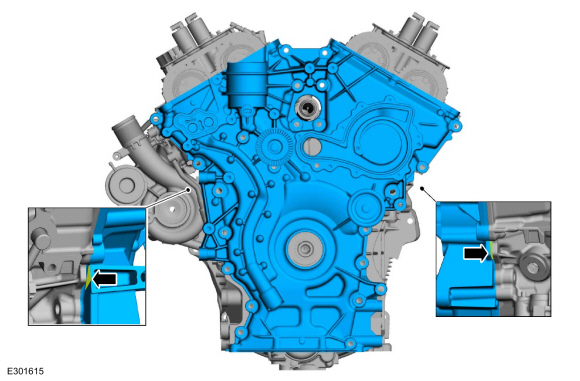
Using a large flat-bladed screwdriver and the
indicated pry pads, release the sealer and remove the engine front
cover.
Use the General Equipment: Flat-Bladed Screwdriver
-
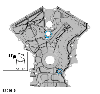
Remove and discard the engine front cover gaskets.
-
Remove and discard the oil gallery seal (6G068).
-
NOTICE:
Only use a 3M™ Roloc® Bristle Disk (2-in white,
part number 07528) to clean the engine front cover. Do not use metal
scrapers, wire brushes or any other power abrasive disk to clean front
cover.
-
Clean the engine front cover using a 3M™ Roloc®
Bristle Disk (2-in white, part number 07528) in a suitable tool turning
at the recommended speed of 15,000 rpm.
Refer to: RTV Sealing Surface Cleaning and Preparation (303-00 Engine System - General Information, General Procedures).
-
Thoroughly wash the engine front cover to remove
any foreign material, including any abrasive particles created during
the cleaning process.
.jpg) |
|
-
NOTICE:
Place clean, lint-free shop towels over exposed
engine cavities. Carefully remove the towels so foreign material is not
dropped into the engine. Any foreign material (including any material
created while cleaning gasket surfaces) that enters the oil passages may
cause engine failure.
NOTICE:
Do not use wire brushes, power abrasive discs or
3M™ Roloc® Bristle Disk (2-in white part number 07528) to clean the
sealing surfaces. These tools cause scratches and gouges that make leak
paths. They also cause contamination that will cause premature engine
failure. Remove all traces of the gasket.
Make sure that the mating faces of the engine block are clean and free of foreign material.
Refer to: RTV Sealing Surface Cleaning and Preparation (303-00 Engine System - General Information, General Procedures).
Use the General Equipment: Plastic Scraper
Installation
LHD AWD/LHD RWD
-
Install new engine front cover gaskets.
-
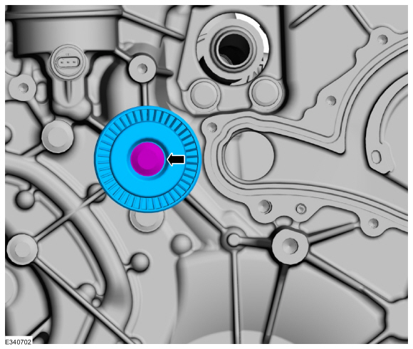
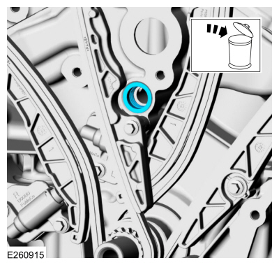
NOTE:
Lubricate the new oil gallery seal with clean engine oil.
Lubricate and install a new oil gallery seal (6G068).
-
NOTICE:
Failure to use Motorcraft® High Performance
Engine RTV Silicone may cause the engine oil to foam excessively and
result in serious engine damage.
NOTE:
The engine front cover must be installed within
10 minutes of applying the sealer and the bolts must be installed and
tightened to 2-5 Nm (18-44 lb-in) within 15 of applying the sealer.
Final tightening of the bolts must be completed within 60 minutes of
applying the sealer. Failure to follow this procedure can cause future
oil leakage.
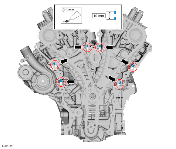
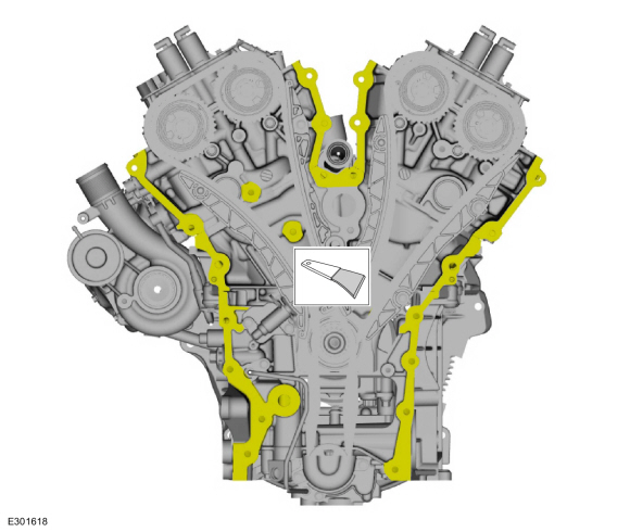
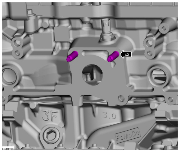
Apply 9 mm (0.35 in) beads of Motorcraft® High
Performance Engine RTV Silicone 10 mm (0.40 in) in length to the
cylinder block skirt-to-cylinder block joints and the cylinder
head-to-cylinder block joints as indicated.
Material: Motorcraft® High Performance Engine RTV Silicone
/ TA-357
(WSE-M4G323-A6)
 |
|
-
NOTICE:
Failure to use Motorcraft® High Performance
Engine RTV Silicone may cause the engine oil to foam excessively and
result in serious engine damage.
NOTE:
The engine front cover must be installed within
10 minutes of applying the sealer and the bolts must be installed and
tightened to 2-5 Nm (18-44 lb-in) within 15 of applying the sealer.
Final tightening of the bolts must be completed within 60 minutes of
applying the sealer. Failure to follow this procedure can cause future
oil leakage.
-
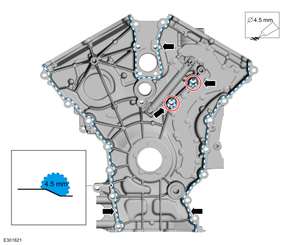
Apply a 4.5 mm (0.18 in) bead of Motorcraft®
High Performance Engine RTV Silicone to the engine front cover sealing
surfaces of the inner bolt bosses.
Material: Motorcraft® High Performance Engine RTV Silicone
/ TA-357
(WSE-M4G323-A6)
-
Apply a 4.5 mm (0.18 in) bead of Motorcraft®
High Performance Engine RTV Silicone to the chamfer of the engine front
cover sealing surfaces.
Material: Motorcraft® High Performance Engine RTV Silicone
/ TA-357
(WSE-M4G323-A6)
 |
|
-
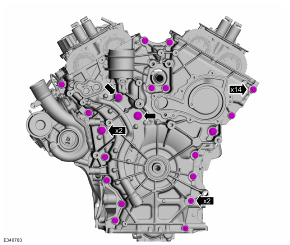
Install the engine front cover and the fasteners.
Torque:
Stage 1:
Tighten bolts 1 through 11 to:
18 lb.ft (24 Nm)
Stage 2:
Tighten bolts 12 through 13 to:
35 lb.ft (48 Nm)
Stage 3:
Tighten bolts 14 through 22 to:
18 lb.ft (24 Nm)
-
Install the idler pulley and bolt.
Torque:
18 lb.ft (24 Nm)
-
Attach the wiring harness retainer.
-
NOTICE:
A new turbocharger oil supply filter must be
installed. Failure to follow these instructions can result in
turbocharger damage.
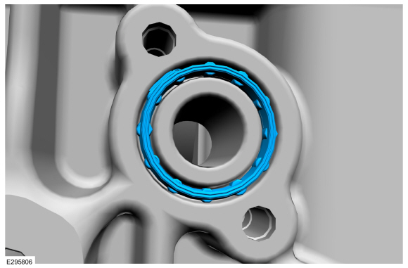
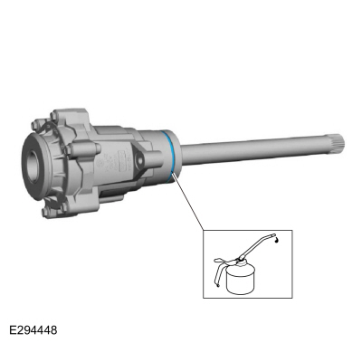
Install the new turbocharger oil supply tube O-ring
seals and the new turbocharger oil supply tube oil filter. Lubricate the
new turbocharger oil supply tube O-ring seals with clean engine oil.
Refer to: Specifications (303-01A Engine - 3.0L EcoBoost, Specifications).
.jpg) |
|
-
NOTICE:
Use brake cleaner and a nylon brush to clean. Do
not use a metal brush, damage to sealing area will result in leaks.
-
Carefully use a nylon brush to remove the old
O-ring residue and use brake cleaner to rinse the O-ring residue out of
the turbocharger tube to turbocharger O-ring bore and the turbocharger
tube to engine O-ring bore. Inspect the area for deep scratches and
gouges. Do not use a metal brush, damage to sealing area will result in
leaks. Install new components if needed.
-
Connect the turbocharger oil supply tube to the
turbocharger, then install and tighten the turbocharger oil supply tube
bolt.
Material: Motorcraft® Metal Brake Parts Cleaner
/ PM-4-A, PM-4-B
Torque:
89 lb.in (10 Nm)
-
Install the turbocharger studs.
Torque:
106 lb.in (12 Nm)
-
-
NOTICE:
Use brake cleaner and a nylon brush to
clean. Do not use a metal brush, damage to sealing area will result in
leaks.
Carefully use a nylon brush to remove the old
O-ring residue and use brake cleaner to rinse the O-ring residue out of
the turbocharger tube to engine O-ring bores for both the oil and
coolant tubes. Inspect the area for deep scratches and gouges. Do not
use a metal brush, damage to sealing area will result in leaks. Install
new components if needed.
Material: Motorcraft® Metal Brake Parts Cleaner
/ PM-4-A, PM-4-B
-
Install the new gasket, the turbocharger and
loosely install the turbocharger nuts. Install the turbocharger oil
supply tube to the engine while installing the turbocharger.
-
Install the turbocharger bolt.
Torque:
44 lb.ft (60 Nm)
-
-
Tighten the turbocharger nut.
Torque:
27 lb.ft (37 Nm)
-
Tighten the turbocharger nut.
Torque:
44 lb.ft (60 Nm)
-
Re-tighten the turbocharger bolt.
Torque:
44 lb.ft (60 Nm)
-
-
Re-tighten the turbocharger nut
Torque:
27 lb.ft (37 Nm)
-
Re-tighten the turbocharger nuts.
Torque:
44 lb.ft (60 Nm)
-
Install a new outer turbocharger coolant supply tube
O-ring seal. Lubricate the O-ring seal and the rubber gasket with clean
engine coolant.
Refer to: Specifications (303-01A Engine - 3.0L EcoBoost, Specifications).
-
NOTICE:
Use brake cleaner and a nylon brush to clean. Do
not use a metal brush, damage to sealing area will result in leaks.
-
Carefully use a nylon brush to remove the old
O-ring residue and use brake cleaner to rinse the O-ring residue out of
the turbocharger tube to engine O-ring bore. Inspect the area for deep
scratches and gouges. Install new components if needed.
-
Install the outer turbocharger coolant supply tube, then install and tighten the bolt.
Material: Motorcraft® Metal Brake Parts Cleaner
/ PM-4-A, PM-4-B
Torque:
89 lb.in (10 Nm)
-
Connect the turbocharger wastegate control hose and clamp.
Use the General Equipment: Hose Clamp Remover/Installer
-
NOTICE:
Do not use a metal brush, damage to sealing area will result in leaks.
-
Carefully use a nylon brush to remove the old
O-ring residue and use brake cleaner to rinse the O-ring residue out of
the turbocharger tube to turbocharger O-ring bore and the turbocharger
tube to engine O-ring bore. Inspect the area for deep scratches and
gouges. Install new components if needed.
-
Install the turbocharger oil supply tube, then install and tighten the oil supply tube bolt.
Material: Motorcraft® Metal Brake Parts Cleaner
/ PM-4-A, PM-4-B
Torque:
89 lb.in (10 Nm)
-
Install a new turbocharger coolant return tube
O-ring seal. Lubricate the new O-ring seal with clean engine coolant.
Refer to: Specifications (303-01A Engine - 3.0L EcoBoost, Specifications).
-
NOTICE:
Do not use a metal brush, damage to sealing area will result in leaks.
-
Carefully use a nylon brush to remove the old
O-ring residue and use brake cleaner to rinse the O-ring residue out of
the turbocharger O-ring bore. Inspect the area for deep scratches and
gouges. Install new components if needed.
Material: Motorcraft® Metal Brake Parts Cleaner
/ PM-4-A, PM-4-B
-
Connect the turbocharger coolant return tube to the turbocharger, then install and tighten the bolt.
Torque:
89 lb.in (10 Nm)
-
Install the turbocharger heat shield and the bolts.
Torque:
89 lb.in (10 Nm)
-
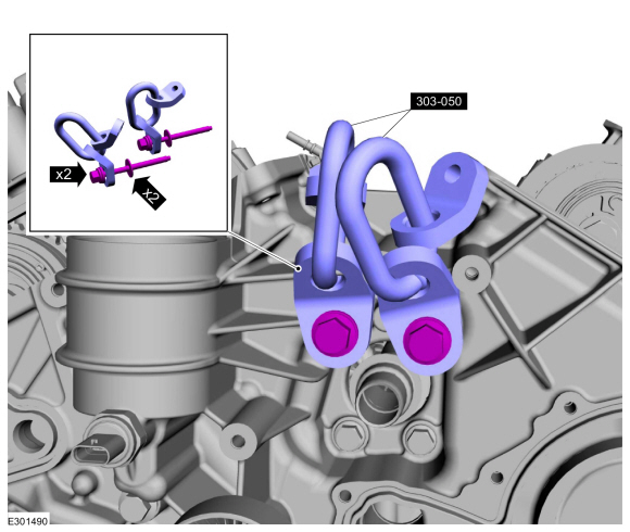
Remove the engine front cover bolts.
-
Using two M8 x 1.25 x 105 mm bolts and two washers, install the special tools to the engine.
Install Special Service Tool: 303-050
(T70P-6000)
Lifting Bracket, Engine.
-
Install Special Service Tool: 303-F070
Support Bar, Engine.
-
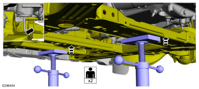
Support the front and rear of the subframe with adjustable jack stands.
-
NOTE:
The original bolts should be retained to be used during the LH catalytic converter.
Remove the rear subframe bolts.
-
Remove the middle subframe bolts.
-
-
Remove the front subframe bolts.
-
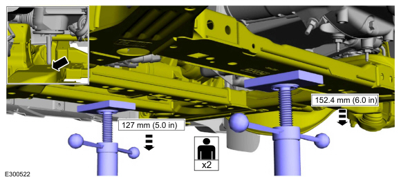
With the aid of an assistant, lower the front jack
stand 127 mm (5.0 in) and the rear jack stand 152.4 mm (6.0 in) evenly
or until engine mount stud clears the subframe.
-
-
Remove the bolts and the LH engine mount.
-
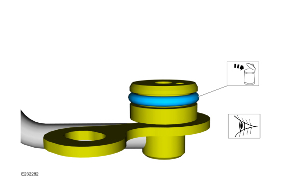
Install the new turbocharger oil return tube-to-engine block gasket.
-
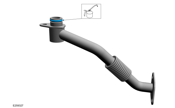
Install a new turbocharger oil return tube O-ring seal, then lubricate with clean engine oil.
Refer to: Specifications (303-01A Engine - 3.0L EcoBoost, Specifications).
-
NOTICE:
Do not use a metal brush, damage to sealing area will result in leaks.
-
Carefully use a nylon brush to remove the old
O-ring residue and use brake cleaner to rinse the O-ring residue out of
the turbocharger O-ring bore. Inspect the area for deep scratches and
gouges.
-
Install the turbocharger oil return tube, then
install and tighten the turbocharger oil return tube bolts.
Material: Motorcraft® Metal Brake Parts Cleaner
/ PM-4-A, PM-4-B
Torque:
89 lb.in (10 Nm)
-
Install the wire harness bracket, then install and tighten the bolt.
Torque:
106 lb.in (12 Nm)
LHD AWD
-
Install a new seal and lubricate.
-
Install the front axle disconnect actuator and the bolts.
Torque:
26 lb.ft (35 Nm)
-
Connect the front axle disconnect actuator electrical connector and vent hose.
LHD AWD/LHD RWD
-
NOTE:
The original rear and middle subframe bolts should be initially installed in the LH engine mount procedure. They will be discarded after the LH catalytic converter is tightened.
Install the LH engine mount.
Refer to: Engine Mount LH (303-01A Engine - 3.0L EcoBoost, Removal and Installation).
LHD AWD
-
NOTE:
LH shown, RH similar.
Install the front suspension height sensors and the bolts.
Torque:
133 lb.in (15 Nm)
-
Install the LH front halfshaft.
Refer to: Halfshaft (205-04 Front Drive Halfshafts, Removal and Installation).
LHD AWD/LHD RWD
-
Install the following items:
-
Refer to: Crankshaft Front Seal (303-01A Engine - 3.0L EcoBoost, Removal and Installation).
-
Refer to: Generator - 3.0L EcoBoost (414-02 Generator and Regulator, Removal and Installation).
-
Refer to: Coolant Pump (303-03A Engine Cooling - 3.0L EcoBoost, Removal and Installation).
-
Refer to: Accessory Drive Belt Tensioner (303-05A Accessory Drive - 3.0L EcoBoost, Removal and Installation).
-
Install the upper and lower radiator hoses and clamps.
-
Install the following items:
-
Refer to: Oil Cooler (303-01A Engine - 3.0L EcoBoost, Removal and Installation).
-
Refer to: Valve Cover LH (303-01A Engine - 3.0L EcoBoost, Removal and Installation).
-
Refer to: Valve Cover RH (303-01A Engine - 3.0L EcoBoost, Removal and Installation).
-
Refer to: Degas Bottle (303-03A Engine Cooling - 3.0L EcoBoost, Removal and Installation).
-
Refer to: Oil Pan (303-01A Engine - 3.0L EcoBoost, Removal and Installation).
-
Install a new engine oil filter and fill the engine with clean engine oil.
Refer to: Engine Oil Draining and Filling (303-01A Engine - 3.0L EcoBoost, General Procedures).
-
Connect the battery ground cable.
Refer to: Battery Disconnect and Connect (414-01 Battery, Mounting and Cables, General Procedures).
-
Pressurize the fuel system.
Refer to: Fuel System Pressure Release (310-00A Fuel System - General Information - 3.0L EcoBoost, General Procedures).
-
Fill and bleed the engine cooling system.
Refer to: Engine Cooling System Draining, Vacuum Filling and Bleeding (303-03A Engine Cooling - 3.0L EcoBoost, General Procedures).
-
Use the Powertrain Control Module (PCM) Misfire
Monitor Profile Correction routine in the diagnostic scan tool.
-
Start and check the exhaust system for leaks.
-
Calibrate the suspension system. Connect the scan
tool and carry out the ride height calibration routine. Follow the scan
tool directions.
Special Tool(s) /
General Equipment
303-050
(T70P-6000)
Lifting Bracket, Engine
303-F070Support Bar, EngineTKIT-1999A-F/LTTKIT-1999A-FM/FLM
Removal
NOTE:
AWD shown, RWD similar...
Other information:
Special Tool(s) /
General Equipment
Air Conditioning Service Unit
Air Conditioning Adaptor Kit
Inspection
Recover the refrigerant. Refer to Air Conditioning (A/C)
System Recovery, Evacuation and Charging procedure in Group 412...
Removal
NOTICE:
During engine repair procedures, cleanliness is extremely
important. Any foreign material, including any material created while
cleaning gasket surfaces, that enters the oil passages, coolant passages
or the oil pan, can cause engine failure...
.jpg)
.jpg)
.jpg)
.jpg)
.jpg)
.jpg)
.jpg)
.jpg)
.jpg)
.jpg)
.jpg)
.jpg)
.jpg)
.jpg)
.jpg)
.jpg)
.jpg)
.jpg)
.jpg)
.jpg)
.jpg)
.jpg)

 Removal and Installation - Engine Mount LH