Lincoln Aviator 2020-2026 Service Manual / Electrical / Electrical Distribution / Module Communications Network / Removal and Installation - Gateway Module A (GWM)
Lincoln Aviator: Module Communications Network / Removal and Installation - Gateway Module A (GWM)
Removal
NOTE: Removal steps in this procedure may contain installation details.
-
NOTE: If installing a new module, it is necessary to upload the module configuration information to the scan tool prior to removing the module. This information must be downloaded into the new module after installation.
Using a diagnostic scan tool, begin the PMI process for the GWM following the on-screen instructions.
-
Remove the retainers and the drivers side insulation panel.
-
Remove the bolt.
Torque: 28 lb.in (3.2 Nm)
-
Remove the nut and the push pins.
Torque: 22 lb.in (2.5 Nm)
-
Disconnect the electrical connector.
-
Remove the bolt.
.jpg) |
-
Remove the nuts and the GWM.
-
Disconnect the electrical connector.
Torque: 28 lb.in (3.2 Nm)
-
Disconnect the electrical connector.
.jpg) |
Installation
-
To install, reverse the removal procedure.
-
Using a diagnostic scan tool, complete the PMI process for the GWM following the on-screen instructions.
Other information:
Lincoln Aviator 2020-2026 Service Manual: Removal and Installation - Rear Wheelhouse Outer
Special Tool(s) / General Equipment Resistance Spotwelding Equipment Spherical Cutter Grinder Hot Air Gun Spatula Air Body Saw 8 mm Drill Bit MIG/MAG Welding Equipment Spot Weld Drill Bit Locking Pliers Materials Name Specification Metal Bonding AdhesiveTA-1, TA-1-B, 3M™ 08115, LORD Fusor® 108B - Seam SealerTA-2-B, 3M™ 08308, LORD Fusor® 803DTM - Flexible Foam Repair3M™ 08463, LORD Fusor® 121 - Removal WARNING: Electric vehicles damaged by a crash may have compromised high voltage safety systems and present a potential high voltage electrical shock hazard...
Lincoln Aviator 2020-2026 Service Manual: Specifications
General Specifications Item Specification Plug Weld hole 8 mm (0.315 in) Weld Wire ER70S-3 0.9 mm (0.0354 in) - 1.1 mm (0.0433 in) Weld Wire ER70S-6 0...
Categories
- Manuals Home
- Lincoln Aviator Owners Manual
- Lincoln Aviator Service Manual
- Child Safety Locks
- Changing the Front Wiper Blades - Vehicles With: Heated Wiper Blades
- Disabling Auto-Start-Stop
- New on site
- Most important about car
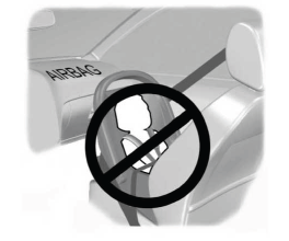
Children and Airbags
WARNING: Airbags can kill or injure a child in a child restraint. Never place a rear-facing child restraint in front of an active airbag. If you must use a forward-facing child restraint in the front seat, move the seat upon which the child restraint is installed all the way back.

Copyright © 2026 www.liaviator2.com


