Lincoln Aviator 2020-2026 Service Manual / Chassis / Brake System / Parking Brake and Actuation / Removal and Installation - Parking Brake Switch
Lincoln Aviator: Parking Brake and Actuation / Removal and Installation - Parking Brake Switch
Special Tool(s) / General Equipment
| Interior Trim Remover |
Removal
NOTE: Removal steps in this procedure may contain installation details.
NOTE: Move the front seats forward and rearward as necessary to access floor console components.
-
Release the retainers and remove the LH floor console side trim panel.
Use the General Equipment: Interior Trim Remover
.jpg) |
-
Release the retainers and remove the RH floor console side trim panel.
Use the General Equipment: Interior Trim Remover
.jpg) |
-
Open the center console arm rest panel.
.jpg) |
-
Remove the FCIMB.
Refer to: Front Controls Interface Module B (FCIMB) (415-00 Information and Entertainment System - General Information, Removal and Installation).
-
Remove both top console side panel bolts.
Torque: 22 lb.in (2.5 Nm)
.jpg) |
-
Remove both top console side trim panels.
-
Remove the bolts.
Use the General Equipment: Interior Trim Remover
Torque: 22 lb.in (2.5 Nm)
-
Release the retainers and remove the RH and LH floor console side trim panels.
-
Remove the bolts.
.jpg) |
-
Remove both floor console bolts.
-
Remove the bolts.
Use the General Equipment: Interior Trim Remover
Torque: 28 lb.in (3.2 Nm)
-
Remove the screws.
Torque: 17 lb.in (1.9 Nm)
-
Remove the bolts.
.jpg) |
-
Release the clips, detach the console top panel,
disconnect the electrical connectors and remove the console top panel.
.jpg) |
-
Remove the bolts and the parking brake switch.
Torque: 17 lb.in (1.9 Nm)
.jpg) |
Installation
-
To install, reverse the removal procedure.
-
NOTE: Anytime the parking brake switch electrical connector has been disconnected, the EPB system is deactivated and a DTC is stored in the EPB module. Perform the following step to restore the EPB system and clear the EPB module DTC.
Apply and release the parking brake twice within 5 seconds, pausing with the switch in the NEUTRAL position for approximately one-half second between each apply and release. Using a diagnostic scan tool, clear the EPB module Diagnostic Trouble Codes (DTCs).
 Removal and Installation - Parking Brake Actuator Motor
Removal
NOTE:
Removal steps in this procedure may contain installation details.
NOTE:
LH side shown, RH similar.
With the vehicle in NEUTRAL, position it on a hoist...
Other information:
Lincoln Aviator 2020-2026 Service Manual: Removal and Installation - Engine Rear Undershield
Removal NOTE: Removal steps in this procedure may contain installation details. Remove the Engine front undershield. Refer to: Engine Front Undershield (501-02 Front End Body Panels, Removal and Installation). Remove the bolts Torque: 22 lb...
Lincoln Aviator 2020-2026 Service Manual: General Procedures - Rear Door Alignment
Adjustment NOTE: Removal steps in this procedure may contain installation details. NOTE: LH side shown, RH side similar. All alignments Open the rear door. Remove the bolts and the striker assembly...
Categories
- Manuals Home
- Lincoln Aviator Owners Manual
- Lincoln Aviator Service Manual
- Interior Lamps
- Description and Operation - Body and Frame
- Opening and Closing the Hood
- New on site
- Most important about car
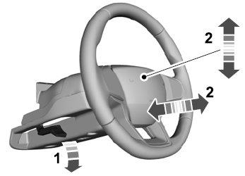
Adjusting the Steering Wheel - Vehicles With: Manual Adjustable Steering Column
WARNING: Do not adjust the steering wheel when your vehicle is moving.
Note: Make sure that you are sitting in the correct position.
Unlock the steering column. Adjust the steering wheel to the desired position.
Copyright © 2026 www.liaviator2.com

