
Lincoln Aviator: Brake System / Parking Brake and Actuation
- Description and Operation - Parking Brake - Overview
- Description and Operation - Parking Brake - Component Location
- Description and Operation - Parking Brake - System Operation and Component Description
- Diagnosis and Testing - Parking Brake
- Removal and Installation - Parking Brake Actuator Motor
- Removal and Installation - Parking Brake Switch
 Removal and Installation - Rear Brake Flexible Hose
Removal
WARNING:
Service actions on vehicles equipped with electronic brake
booster and electronic parking brakes may cause unexpected brake
application, which could result in injury to hands or fingers...
 Description and Operation - Parking Brake - Overview
Overview
The
parking brake system uses 2 switch activated, Electronic Control Unit
(ECU) controlled motors to apply and release the rear brake calipers...
Other information:
Lincoln Aviator 2020-2026 Service Manual: Removal and Installation - Main Control Valve Body
Removal NOTE: The Solenoid Body Strategy Data Download procedure must be performed if a new main control valve body is installed. Remove the transmission fluid pan gasket and filter. Refer to: Transmission Fluid Pan, Gasket and Filter (307-01A Automatic Transmission - 10-Speed Automatic Transmission – 10R60, Removal and Installation)...
Lincoln Aviator 2020-2026 Service Manual: Diagnosis and Testing - Reversing Lamps
Diagnostic Trouble Code (DTC) Chart Diagnostics in this manual assume a certain skill level and knowledge of Ford-specific diagnostic practices. REFER to: Diagnostic Methods (100-00 General Information, Description and Operation). Diagnostic Trouble Code Chart Module DTC Description Action BCM B1277:11 Reverse Lamp: Circuit Short To Ground GO to Pinpoint Test A BCM B1277:15 Reverse Lamp: Circuit Short To Battery or Open GO to Pinpoint Test A Symptom Charts Diagnostics in this manual assume a certain skill level and knowledge of Ford-specific diagnostic practices...
Categories
- Manuals Home
- Lincoln Aviator Owners Manual
- Lincoln Aviator Service Manual
- Changing the Front Wiper Blades - Vehicles With: Heated Wiper Blades
- Fuel Quality
- General Procedures - Transmission Fluid Drain and Refill
- New on site
- Most important about car
Locking and Unlocking the Doors from Inside
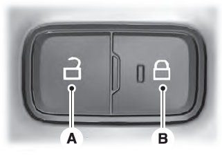
Locking the Doors
Press the lock switch on the door interior trim panel. The doors can no longer be released using the exterior door handle switches and the luggage compartment locks.

Copyright © 2026 www.liaviator2.com