Lincoln Aviator: Rear Disc Brake / Removal and Installation - Rear Brake Flexible Hose
Removal
.jpg) WARNING:
Service actions on vehicles equipped with electronic brake
booster and electronic parking brakes may cause unexpected brake
application, which could result in injury to hands or fingers. Put the
brake system into service mode prior to servicing or removing any brake
components. Failure to follow this instruction may result in serious
personal injury.
WARNING:
Service actions on vehicles equipped with electronic brake
booster and electronic parking brakes may cause unexpected brake
application, which could result in injury to hands or fingers. Put the
brake system into service mode prior to servicing or removing any brake
components. Failure to follow this instruction may result in serious
personal injury.
NOTICE: Do not allow the brake fluid to come in contact with the adhesive backing on the brake pads. This may prevent the brake pad adhesive surface from bonding with the brake caliper. If brake fluid is spilled onto the brake pads, install new pads.
NOTICE: If the fluid is spilled on the paintwork, the affected area must be immediately washed down with cold water.
NOTE: Make sure all openings are sealed.
NOTE: Removal steps in this procedure may contain installation details.
-
Activate the brake service mode.
Refer to: Brake Service Mode Activation and Deactivation (206-00 Brake System - General Information, General Procedures).
-
Remove the wheel and tire.
Refer to: Wheel and Tire (204-04A Wheels and Tires, Removal and Installation).
-
Remove the flow bolt and detach the brake hose. Discard the washers.
Torque: 26 lb.ft (35 Nm)
.jpg) |
-
Remove the nut and the retainer and position aside the rear brake electrical harness.
Torque: 62 lb.in (7 Nm)
.jpg) |
-
-
Remove the nut and disconnect the brake tube.
Torque: 159 lb.in (18 Nm)
-
Remove the bolt.
Torque: 80 lb.in (9 Nm)
-
Remove the bracket mounting bolt and the rear brake flexible hose.
Torque: 133 lb.in (15 Nm)
-
Remove the nut and disconnect the brake tube.
.jpg) |
Installation
-
NOTE: If equipped, verify correct installation of the brake flexible hose protective sleeve and tie strap.
To install, reverse the removal procedure.
-
Deactivate the brake service mode.
Refer to: Brake Service Mode Activation and Deactivation (206-00 Brake System - General Information, General Procedures).
-
Bleed the brake system.
Refer to: Brake System Pressure Bleeding (206-00 Brake System - General Information, General Procedures).
 Removal and Installation - Brake Pads
Removal
WARNING:
Service actions on vehicles equipped with electronic brake
booster and electronic parking brakes may cause unexpected brake
application, which could result in injury to hands or fingers...
Other information:
Lincoln Aviator 2020-2026 Service Manual: General Procedures - Door Latch Lubrication
Special Tool(s) / General Equipment Flat-Bladed Screwdriver Materials Name Specification Motorcraft® Multi-Purpose Grease SprayXL-5-A ESB-M1C93-B Activation NOTE: Typical left front door shown, others similar. Open the door...
Lincoln Aviator 2020-2026 Owners Manual: Notice to utility vehicle and truck owners
WARNING: Vehicles with a higher center of gravity (utility and four-wheel drive vehicles) handle differently than vehicles with a lower center of gravity (passenger cars). Avoid sharp turns, excessive speed and abrupt steering in these vehicles...
Categories
- Manuals Home
- Lincoln Aviator Owners Manual
- Lincoln Aviator Service Manual
- Description and Operation - Jacking and Lifting
- Disabling Auto-Start-Stop
- Fuel Quality
- New on site
- Most important about car
Children and Airbags
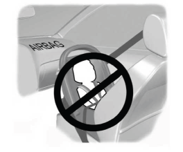
WARNING: Airbags can kill or injure a child in a child restraint. Never place a rear-facing child restraint in front of an active airbag. If you must use a forward-facing child restraint in the front seat, move the seat upon which the child restraint is installed all the way back.


