Lincoln Aviator: Rear Disc Brake / Removal and Installation - Brake Pads
Removal
.jpg) WARNING:
Service actions on vehicles equipped with electronic brake
booster and electronic parking brakes may cause unexpected brake
application, which could result in injury to hands or fingers. Put the
brake system into service mode prior to servicing or removing any brake
components. Failure to follow this instruction may result in serious
personal injury.
WARNING:
Service actions on vehicles equipped with electronic brake
booster and electronic parking brakes may cause unexpected brake
application, which could result in injury to hands or fingers. Put the
brake system into service mode prior to servicing or removing any brake
components. Failure to follow this instruction may result in serious
personal injury.
-
Activate the brake service mode.
Refer to: Brake Service Mode Activation and Deactivation (206-00 Brake System - General Information, General Procedures).
-
Remove the wheel and tire.
Refer to: Wheel and Tire (204-04A Wheels and Tires, Removal and Installation).
-
Detach the parking brake motor electrical connector.
.jpg) |
-
NOTICE: Do not use a C-clamp to compress the brake caliper piston or damage to the parking brake actuator may occur.
NOTICE: Do not pry in the caliper sight hole to retract the pistons as this can damage the pistons and boots.
NOTICE: Do not allow the brake caliper to hang from the brake hose or damage to the hose can occur.
NOTICE: Do not manually retract the piston
Remove and discard the brake caliper mounting bolts.
.jpg) |
-
Remove the brake pads.
.jpg) |
-
Remove the brake pad clips. Discard if installing new brake pads.
.jpg) |
Installation
NOTICE: Do not use a C-clamp to compress the brake caliper piston or damage to the parking brake actuator motor may occur.
NOTICE: Do not manually retract the piston or damage to the parking brake actuator may occur.
NOTICE: Make sure that the brake hose is not twisted when installing the brake caliper or damage to the brake flexible hose may occur.
NOTE: If installing new brake pads, make sure to install all new hardware supplied with the brake pad kit.
-
Clean the brake pad-to-anchor plate contact points.
.jpg) |
-
NOTE: Clips should sit flat against the bracket with the retraction leg loop toward the outside of bracket.
-
Install all clips with retraction leg loop toward
outside of bracket. Center the abutment clips over the bracket recess.
-
Start to install the clip from the top rail.
-
Install the clip over the lower abutment.
-
Apply pressure with fingers to fully seat the clip against bracket.
-
Install all clips with retraction leg loop toward
outside of bracket. Center the abutment clips over the bracket recess.
.jpg) |
-
-
Install the brake pads at a downward angle to the caliper without touching the edge of the abutment clip.
-
Compress the spring leg of the clip with the bottom
of the pad at the abutment surface and rotate the top of the pad into
position.
-
Install the brake pads at a downward angle to the caliper without touching the edge of the abutment clip.
.jpg) |
-
Install the brake caliper and tighten the guide pin bolts.
Torque: 26 lb.ft (35 Nm)
.jpg) |
-
Deactivate the brake service mode.
Refer to: Brake Service Mode Activation and Deactivation (206-00 Brake System - General Information, General Procedures).
- Apply the brake pedal several times to verify correct brake system operation.
-
Install the wheel and tire.
Refer to: Wheel and Tire (204-04A Wheels and Tires, Removal and Installation).
 Removal and Installation - Brake Disc Shield
Removal
NOTE:
Removal steps in this procedure may contain installation details.
Remove the wheel bearing and wheel hub.
Refer to: Wheel Bearing and Wheel Hub (204-02 Rear Suspension, Removal and Installation)...
 Removal and Installation - Rear Brake Flexible Hose
Removal
WARNING:
Service actions on vehicles equipped with electronic brake
booster and electronic parking brakes may cause unexpected brake
application, which could result in injury to hands or fingers...
Other information:
Lincoln Aviator 2020-2026 Service Manual: Specifications
Lubricants, Fluids, Sealers and Adhesives Item Specification Transfer case fluid Material: Motorcraft® MERCON® LV Automatic Transmission Fluid / XT-10-QLVC (WSS-M2C938-A) (MERCON® LV, ) Capacities Liters Transfer case - Service fill 1...
Lincoln Aviator 2020-2026 Service Manual: Removal and Installation - Transfer Case Front Output Shaft Seal
Special Tool(s) / General Equipment 205-1018Installation Tube 205-1067Installer, Output Shaft AWD Removal With the vehicle in NEUTRAL, position it on a hoist. Refer to: Jacking and Lifting (100-02 Jacking and Lifting, Description and Operation)...
Categories
- Manuals Home
- Lincoln Aviator Owners Manual
- Lincoln Aviator Service Manual
- Remove and Reinstall the Battery
- Garage Door Opener
- Resetting the System
- New on site
- Most important about car
Child Seats

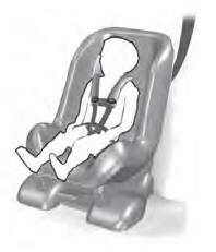
Use a child restraint (sometimes called an infant carrier, convertible seat, or toddler seat) for infants, toddlers and children weighing 40 lb (18 kg) or less (generally four-years-old or younger).
Using Lap and Shoulder Belts
WARNING: Do not place a rearward facing child restraint in front of an active airbag. Failure to follow this instruction could result in personal injury or death.
