
Lincoln Aviator 2020-2026 Service Manual / Chassis / Suspension / Tire Pressure Monitoring System (TPMS) / General Procedures - Tire Pressure Monitoring System (TPMS) Sensor Location Calibration

Lincoln Aviator: Tire Pressure Monitoring System (TPMS) / General Procedures - Tire Pressure Monitoring System (TPMS) Sensor Location Calibration

Special Tool(s) / General Equipment

204-D081A (204-D081)
Tire Pressure Monitor (TPMS)
Ford Diagnostic Equipment

Programming

NOTE: The TPMS can be placed into learn mode using a diagnostic scan tool or manually where a diagnostic scan tool is not available.

NOTE: The horn will sound once and the TPMS indicator will flash if the training mode has been entered successfully. If equipped, the message center will display TRAIN Left Front (LF) TIRE.

  1. NOTE: Enter Training Mode With IDS Scan Tool

    1. Select Chassis.
    1. Select TPMS.
    1. Select Training Mode.
      Use the General Equipment: Ford Diagnostic Equipment
  1. NOTE: Enter Training Mode With FDRS Scan Tool

    1. Select Toolbox.
    1. Select BCM.
    1. Select BCM — TPMS Initialization.
      Use the General Equipment: Ford Diagnostic Equipment

Programming

NOTE: Enter Training Mode Without Scan Tool

  1. NOTE: The horn will sound once and the TPMS indicator will flash if the training mode has been entered successfully. If equipped, the message center will display TRAIN Left Front (LF) TIRE.

    With the ignition OFF, press and release the brake pedal.
  1. Using the start/stop switch, position the ignition from OFF to RUN 3 times, ending in the RUN position.
  1. Press and release the brake pedal.
  1. Position the ignition to OFF position.
  1. Using the start/stop switch, position the ignition from OFF to RUN 3 times, ending in the RUN position.

Programming

NOTE: TPMS Sensor Training Procedure

  1. NOTE: It may take up to 6 seconds to activate a tire pressure sensor. During this time, the special tool must remain in place at the valve stem.

    Place the special tool on the Left Front (LF) tire sidewall at the valve stem. Press and release the test button on the special tool. The horn will sound briefly to indicate that the tire pressure sensor has been recognized by the BCM.
    Use Special Service Tool: 204-D081A (204-D081)  Tire Pressure Monitor (TPMS).
  1. Within 2 minutes of the horn sounding, place the special tool on the Right Front (RF) tire sidewall at the valve stem and press and release the test button to train the Right Front (RF) tire pressure sensor.
    Use Special Service Tool: 204-D081A (204-D081)  Tire Pressure Monitor (TPMS).
  1. Repeat Step 1 for the Right Rear (RR) and Left Rear (LR) tires. The procedure is completed after the last tire has been trained. When the training procedure is complete, the message center (if equipped) will display TIRE TRAINING COMPLETE. For vehicles not equipped with a message center, successful completion of the training procedure will be verified by positioning the ignition to OFF without the horn sounding. If the horn sounds twice when the ignition is positioned to OFF, the training procedure was not successful.
  1. Using the scan tool, locate the updated TPMS sensor identifiers trained to the BCM and document them on the applicable warranty claim.
    Use Special Service Tool: 204-D081A (204-D081)  Tire Pressure Monitor (TPMS).
  1. NOTE: This step is required to clear DTC B1182:55, cause the BCM to exit the manufacturing mode and to make sure there are no other concerns with a newly programmed BCM.

    If the sensors are being trained due to the installation of a new BCM, clear any DTC and carry out the BCM On-Demand Self Test.

    General Procedures - Tire Pressure Monitoring System (TPMS) Sensor Activation

    Special Tool(s) / General Equipment 204-D081A (204-D081) Tire Pressure Monitor (TPMS) Activation NOTE: The tire pressure sensors will go into a "sleep mode" when a vehicle is stationary to conserve battery power...

    Removal and Installation - Tire Pressure Monitoring System (TPMS) Sensor

    Removal   WARNING: The Tire Pressure Monitoring System (TPMS) sensor battery may release hazardous chemicals if exposed to extreme mechanical damage...

    Other information:

    Lincoln Aviator 2020-2026 Service Manual: Diagnosis and Testing - Vehicle Dynamic Suspension - Vehicles With: Air Suspension


    Diagnostic Trouble Code (DTC) Chart Diagnostics in this manual assume a certain skill level and knowledge of Ford-specific diagnostic practices. REFER to: Diagnostic Methods (100-00 General Information, Description and Operation).   Diagnostic Trouble Code Chart Module   DTC Description Action   SUMA B1041:52 Levelling Control: Not Activated   GO to Pinpoint Test W   SUMA C1043:00 Pressure Decrease Too Slow From Reservoir: No Sub Type Information   GO to Pinpoint Test M   SUMA C104C:11 Left Rear Spring Rate Valve: Circuit Short To Ground   GO to Pinpoint Test E   SUMA C104C:12 Left Rear Spring Rate Valve: Circuit Short To Battery   GO to Pinpoint Test E   SUMA C104C:13 Left Rear Spring Rate Valve: Circuit Open   GO to Pinpoint Test E   SUMA C104C:1A Left Rear Spring Rate Valve: Circuit Resistance Below Threshold   GO to Pinpoint Test E   SUMA C104C:1F Left Rear Spring Rate Valve: Circuit Intermittent   GO to Pinpoint Test E   SUMA C104D:11 Right Front Spring Rate Valve: Circuit Short To Ground   GO to Pinpoint Test D   SUMA C104D:12 Right Front Spring Rate Valve: Circuit Short To Battery   GO to Pinpoint Test D   SUMA C104D:13 Right Front Spring Rate Valve: Circuit Open   GO to Pinpoint Test D   SUMA C104D:1A Right Front Spring Rate Valve: Circuit Resistance Below Threshold   GO to Pinpoint Test D   SUMA C104D:1F Right Front Spring Rate Valve: Circuit Intermittent   GO to Pinpoint Test D   SUMA C104E:11 Right Rear Spring Rate Valve: Circuit Short To Ground   GO to Pinpoint Test F   SUMA C104E:12 Right Rear Spring Rate Valve: Circuit Short To Battery   GO to Pinpoint Test F   SUMA C104E:13 Right Rear Spring Rate Valve: Circuit Open   GO to Pinpoint Test F   SUMA C104E:1A Right Rear Spring Rate Valve: Circuit Resistance Below Threshold   GO to Pinpoint Test F   SUMA C104E:1F Right Rear Spring Rate Valve: Circuit Intermittent   GO to Pinpoint Test F   SUMA C104F:11 Left Front Spring Rate Valve: Circuit Short To Ground   GO to Pinpoint Test C   SUMA C104F:12 Left Front Spring Rate Valve: Circuit Short To Battery   GO to Pinpoint Test C   SUMA C104F:13 Left Front Spring Rate Valve: Circuit Open   GO to Pinpoint Test C   SUMA C104F:1A Left Front Spring Rate Valve: Circuit Resistance Below Threshold   GO to Pinpoint Test C   SUMA C104F:1F Left Front Spring Rate Valve: Circuit Intermittent   GO to Pinpoint Test C   SUMA C1124:07 Height Sensor(s): Mechanical Failures   GO to Pinpoint Test G   SUMA C1124:11 Height Sensor(s): Circuit Short To Ground   GO to Pinpoint Test H   SUMA C1124:12 Height Sensor(s): Circuit Short To Battery   GO to Pinpoint Test H   SUMA C1124:54 Height Sensor(s): Missing Calibration   GO to Pinpoint Test U   SUMA C1A03:2A Left Front Height Sensor: Stuck in Range   GO to Pinpoint Test I   SUMA C1A03:34 Left Front Height Sensor: Signal High Time Less Than Minimum   GO to Pinpoint Test I   SUMA C1A03:35 Left Front Height Sensor: Signal High Time Greater Than Maximum   GO to Pinpoint Test I   SUMA C1A03:36 Left Front Height Sensor: Signal Frequency Too Low   GO to Pinpoint Test I   SUMA C1A03:37 Left Front Height Sensor: Signal Frequency Too High   GO to Pinpoint Test I   SUMA C1A03:84 Left Front Height Sensor: Signal Below Allowable Range   GO to Pinpoint Test I   SUMA C1A03:85 Left Front Height Sensor: Signal Above Allowable Range   GO to Pinpoint Test I   SUMA C1A04:2A Right Front Height Sensor: Stuck in Range   GO to Pinpoint Test J   SUMA C1A04:34 Right Front Height Sensor: Signal High Time Less Than Minimum   GO to Pinpoint Test J   SUMA C1A04:35 Right Front Height Sensor: Signal High Time Greater Than Maximum   GO to Pinpoint Test J   SUMA C1A04:36 Right Front Height Sensor: Signal Frequency Too Low   GO to Pinpoint Test J   SUMA C1A04:37 Right Front Height Sensor: Signal Frequency Too High   GO to Pinpoint Test J   SUMA C1A04:84 Right Front Height Sensor: Signal Below Allowable Range   GO to Pinpoint Test J   SUMA C1A04:85 Right Front Height Sensor: Signal Above Allowable Range   GO to Pinpoint Test J   SUMA C1A05:2A Left Rear Height Sensor: Stuck in Range   GO to Pinpoint Test K   SUMA C1A05:34 Left Rear Height Sensor: Signal High Time Less Than Minimum   GO to Pinpoint Test K   SUMA C1A05:35 Left Rear Height Sensor: Signal High Time Greater Than Maximum   GO to Pinpoint Test K   SUMA C1A05:36 Left Rear Height Sensor: Signal Frequency Too Low   GO to Pinpoint Test K   SUMA C1A05:37 Left Rear Height Sensor: Signal Frequency Too High   GO to Pinpoint Test K   SUMA C1A05:84 Left Rear Height Sensor: Signal Below Allowable Range   GO to Pinpoint Test K   SUMA C1A05:85 Left Rear Height Sensor: Signal Above Allowable Range   GO to Pinpoint Test K   SUMA C1A06:2A Right Rear Height Sensor: Stuck in Range   GO to Pinpoint Test L   SUMA C1A06:34 Right Rear Height Sensor: Signal High Time Less Than Minimum   GO to Pinpoint Test L   SUMA C1A06:35 Right Rear Height Sensor: Signal High Time Greater Than Maximum   GO to Pinpoint Test L   SUMA C1A06:36 Right Rear Height Sensor: Signal Frequency Too Low   GO to Pinpoint Test L   SUMA C1A06:37 Right Rear Height Sensor: Signal Frequency Too High   GO to Pinpoint Test L   SUMA C1A06:84 Right Rear Height Sensor: Signal Below Allowable Range   GO to Pinpoint Test L   SUMA C1A06:85 Right Rear Height Sensor: Signal Above Allowable Range   GO to Pinpoint Test L   SUMA C1A20:00 Pressure Increase Too Slow When Filling Reservoir: No Sub Type Information   GO to Pinpoint Test M   SUMA C1A27:09 Compressor: Component Failures   GO to Pinpoint Test N   SUMA C1A27:63 Compressor: Circuit/Component Protection Time-Out   GO to Pinpoint Test N   SUMA C1A27:98 Compressor: Component Or System Over Temperature   GO to Pinpoint Test N   SUMA C1A27:99 Compressor: Exceeded Learning Limit   GO to Pinpoint Test N   SUMA C1A31:63 Left Front Corner Valve: Circuit/Component Protection Time-Out   GO to Pinpoint Test AD   SUMA C1A32:63 Right Front Corner Valve: Circuit/Component Protection Time-Out   GO to Pinpoint Test AD   SUMA C1A33:63 Left Rear Corner Valve: Circuit/Component Protection Time-Out   GO to Pinpoint Test AD   SUMA C1A34:63 Right Rear Corner Valve: Circuit/Component Protection Time-Out   GO to Pinpoint Test AD   SUMA C1A36:63 Exhaust Valve: Circuit/Component Protection Time-Out   GO to Pinpoint Test AD   SUMA U0100:87 Lost Communication With ECM / PCM: Missing Message   GO to Pinpoint Test O   SUMA U0121:87 Lost Communication With Anti-Lock Brake System (ABS) Control Module: Missing Message   GO to Pinpoint Test P   SUMA U0122:87 Lost Communication With Vehicle Dynamics Control Module: Missing Message   GO to Pinpoint Test Q   SUMA U0131:87 Lost Communication With Power Steering Control Module "A": Missing Message   GO to Pinpoint Test R   SUMA U0140:87 Lost Communication With Body Control Module: Missing Message   GO to Pinpoint Test S   SUMA U0146:87 Lost Communication With Serial Data Gateway "A": Missing Message   GO to Pinpoint Test T   SUMA U0401:00 Invalid Data Received from ECM/PCM A: No Sub Type Information   GO to Pinpoint Test X   SUMA U0415:00 Invalid Data Received from Anti-Lock Brake System (ABS) Control Module "A": No Sub Type Information   GO to Pinpoint Test Y   SUMA U0416:00 Invalid Data Received From Vehicle Dynamics Control Module: No Sub Type Information   GO to Pinpoint Test Z   SUMA U0420:00 Invalid Data Received from Power Steering Control Module "A": No Sub Type Information   GO to Pinpoint Test AA   SUMA U0422:00 Invalid Data Received From Body Control Module: No Sub Type Information   GO to Pinpoint Test AB   SUMA U0447:00 Invalid Data Received From Serial Data Gateway "A": No Sub Type Information   GO to Pinpoint Test AC   SUMA U2100:00 Initial Configuration Not Complete: No Sub Type Information   GO to Pinpoint Test V   SUMA U2100:56 Initial Configuration Not Complete: Invalid/Incompatible Configuration   GO to Pinpoint Test V   SUMA U3000:04 Control Module: System Internal Failures   GO to Pinpoint Test V   SUMA U3000:45 Control Module: Program Memory Failure   GO to Pinpoint Test V   SUMA U3000:46 Control Module: Calibration/Parameter Memory Failure   GO to Pinpoint Test V   SUMA U3000:47 Control Module: Watchdog/Safety µC Failure   GO to Pinpoint Test V   SUMA U3000:48 Control Module: Supervision Software Failure   GO to Pinpoint Test V   SUMA U3003:16 Battery Voltage: Circuit Voltage Below Threshold   GO to Pinpoint Test A   SUMA U3003:17 Battery Voltage: Circuit Voltage Above Threshold   GO to Pinpoint Test B Symptom Chart Symptom Chart: Vehicle Dynamic Suspension Diagnostics in this manual assume a certain skill level and knowledge of Ford-specific diagnostic practices...

    Lincoln Aviator 2020-2026 Owners Manual: Bluetooth Stereo or USB


    Bluetooth Stereo and USB allow you to access media that you store on your Bluetooth device or USB device such as music, audio books or podcasts. The following buttons are available for Bluetooth and USB: You can use the forward, reverse, pause or play buttons to control the audio playback...

    Categories

    Fastening the Seatbelts

    The front outboard and rear safety restraints in the vehicle are combination lap and shoulder belts.

    Insert the belt tongue into the proper buckle (the buckle closest to the direction the tongue is coming from) until you hear a snap and feel it latch. Make sure that you securely fasten the tongue in the buckle.
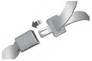
    Lincoln Aviator. Fastening the Seatbelts

    To unfasten, press the release button and remove the tongue from the buckle.

    read more

     
    Copyright © 2026 www.liaviator2.com