Lincoln Aviator: Tire Pressure Monitoring System (TPMS) / Removal and Installation - Tire Pressure Monitoring System (TPMS) Sensor
Removal
-
.jpg) WARNING:
The Tire Pressure Monitoring System (TPMS) sensor
battery may release hazardous chemicals if exposed to extreme mechanical
damage. If these chemicals contact the skin or eyes, flush immediately
with water for a minimum of 15 minutes and get prompt medical attention.
If any part of the battery is swallowed, contact a physician
immediately. When disposing of Tire Pressure Monitoring System (TPMS)
sensors, follow the correct procedures for hazardous material disposal.
Failure to follow these instructions may result in serious personal
injury.
WARNING:
The Tire Pressure Monitoring System (TPMS) sensor
battery may release hazardous chemicals if exposed to extreme mechanical
damage. If these chemicals contact the skin or eyes, flush immediately
with water for a minimum of 15 minutes and get prompt medical attention.
If any part of the battery is swallowed, contact a physician
immediately. When disposing of Tire Pressure Monitoring System (TPMS)
sensors, follow the correct procedures for hazardous material disposal.
Failure to follow these instructions may result in serious personal
injury.
NOTE: The Tire Pressure Monitoring System (TPMS) sensor cannot be removed without disassembly of the wheel and tire.
Disassemble the wheel and tire.
Refer to: Wheel and Tire (204-04A Wheels and Tires, Disassembly and Assembly).
Installation
-
NOTE: The Tire Pressure Monitoring System (TPMS) sensor cannot be installed without disassembly of the wheel and tire.
Assemble the wheel and tire.
Refer to: Wheel and Tire (204-04A Wheels and Tires, Disassembly and Assembly).
 General Procedures - Tire Pressure Monitoring System (TPMS) Sensor Location Calibration
Special Tool(s) /
General Equipment
204-D081A
(204-D081)
Tire Pressure Monitor (TPMS)
Ford Diagnostic Equipment
Programming
NOTE:
The TPMS can be placed into learn mode using a diagnostic scan tool or manually where a diagnostic scan tool is not available...

Other information:
Lincoln Aviator 2020-2026 Owners Manual: Remote Start
WARNING: Do not start the engine in a closed garage or in other enclosed areas. Exhaust fumes are toxic. Always open the garage door before you start the engine. Failure to follow this instruction could result in personal injury or death. The remote start button is on the remote control...
Lincoln Aviator 2020-2026 Service Manual: Removal and Installation - Hood
Removal NOTE: Removal steps in this procedure may contain installation details. On both sides. Index-mark the hood hinge location to aid in hood installation. Remove the clips and the hood struts. Remove the nuts and the hood...
Categories
- Manuals Home
- Lincoln Aviator Owners Manual
- Lincoln Aviator Service Manual
- Body and Paint
- Wireless Accessory Charger (If Equipped)
- Tire Change Procedure
- New on site
- Most important about car
Activating Intelligent Access
The intelligent access key must be within 3 ft (1 m) of the door or luggage compartment you intend to lock or unlock.
At a Door
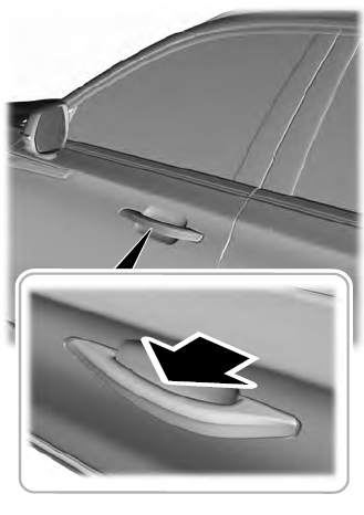
Electronic door handles are on each door. Gently depress the switch inside the exterior door handle to unlock and open the door. An unlock symbol illuminates on the door window trim indicating your vehicle is unlocked.