Lincoln Aviator: Rear Climate Control / Removal and Installation - Rear Climate Control Housing
Removal
NOTICE: During the removal or installation of components, cap, tape or otherwise appropriately protect all openings and tubes/fittings to prevent the ingress of dirt or other contamination. Remove caps, tape and other protective materials prior to installation.
NOTE: Removal steps in this procedure may contain installation details.
-
Recover the refrigerant. Refer to the appropriate Recovery procedure in Group 412.
-
Drain the cooling system.
Refer to: Engine Cooling System Draining, Vacuum Filling and Bleeding (303-03A Engine Cooling - 3.0L EcoBoost, General Procedures).
Refer to: Engine Cooling System Draining, Vacuum Filling and Bleeding (303-03A Engine Cooling - 3.0L EcoBoost, General Procedures).
-
Remove the RHR wheel and tire.
Refer to: Wheel and Tire (204-04A Wheels and Tires, Removal and Installation).
-
Remove the retainers and position aside RHR wheel splashshield.
.jpg) |
-
-
Release the clamps, disconnect the rear heater inlet and outlet lines.
-
Remove the rear evaporator inlet and outlet line nuts and disconnect the fitting.
-
Make sure to cover any open ports to prevent debris from entering the system.
Torque: 133 lb.in (15 Nm)
-
Release the clamps, disconnect the rear heater inlet and outlet lines.
.jpg) |
-
Remove the floorpan bracket nuts.
Torque: 80 lb.in (9 Nm)
.jpg) |
-
Remove the RH loadspace trim panel.
Refer to: Loadspace Trim Panel (501-05 Interior Trim and Ornamentation, Removal and Installation).
-
NOTE: Explorer shown, Aviator similar.
-
Detach the rear floor duct.
-
Detach the duct.
-
Disconnect the rear climate control housing electrical connectors.
-
Detach the wiring harness routing clips.
-
Remove the retainers and remove the rear climate control housing.
Torque: 62 lb.in (7 Nm)
-
Detach the rear floor duct.
.jpg) |
Installation
-
NOTE: Replace the pass-through floor seal with new if seal is removed or damaged.
To install, reverse the removal procedure.
-
NOTICE: Only use the specified material to lubricate the seals.
Install and lubricate new O-ring seals. Refer to the appropriate Specifications in Group 412.
-
Fill and bleed the cooling system.
Refer to: Engine Cooling System Draining, Vacuum Filling and Bleeding (303-03A Engine Cooling - 3.0L EcoBoost, General Procedures).
Refer to: Engine Cooling System Draining, Vacuum Filling and Bleeding (303-03A Engine Cooling - 3.0L EcoBoost, General Procedures).
-
Lubricate the refrigerant system with the correct amount
of clean refrigerant oil. Refer to the appropriate Refrigerant Oil
Adding procedure in Group 412.
 Removal and Installation - Rear Blower Motor Speed Control
Removal
NOTE:
Removal steps in this procedure may contain installation details.
Remove the RH loadspace trim panel.
Refer to: Liftgate Trim Panel (501-05 Interior Trim and Ornamentation, Removal and Installation)...
 Removal and Installation - Rear Evaporator
Removal
NOTE:
Removal steps in this procedure may contain installation details.
Remove the rear climate control housing.
Refer to: Rear Climate Control Housing (412-02A Rear Climate Control, Removal and Installation)...
Other information:
Lincoln Aviator 2020-2026 Service Manual: Specifications
Lubricants, Fluids, Sealers and Adhesives NOTE: Per the warranty and policy manual the Ford Engineering-approved refrigerant (see table for service part number) must be used for air conditioning repairs Item Specifications Motorcraft® R-1234yf Refrigerant POE Oil / YN-34 (US, Canada) WSS-M2C31-B2 Motorcraft® R-1234yf Refrigerant PAG Oil / YN-35 (US, Canada) WSS-M2C300-A2 Motorcraft® Electric A/C Compressor Oil / YN-32 (Mexico, Asia Pacific) _ Motorcraft® PAG Refrigerant Compressor Oil / YN-12-D (Mexico, Asia Pacific) WSH-M1C231-B R-1234yf Refrigerant / YN-33-A (US); HS7Z-19B519-BA (Canada) WSS-M17B21-A Motorcraft® R-134a Refrigerant / MYN-19 (Mexico, Asia Pacific) WSH-M17B19-A Motorcraft® A/C System Flushing Solvent / YN-23 _ Motorcraft® A/C Cooling Coil Coating / YN-29 _ Capacities Item Specifications Motorcraft® R-1234yf Refrigerant PAG Oil / YN-35 (US, Canada) 3...
Lincoln Aviator 2020-2026 Service Manual: Diagnosis and Testing - Battery
General Equipment Diagnostic Battery Charger Use Ford approved battery test equipment. Midtronics MDX-650 or P-300/P-600/490/1050 Midtronics GRX-3590 or 3000 Diagnostics in this manual assume a certain skill level and knowledge of Ford-specific diagnostic practices...
Categories
- Manuals Home
- Lincoln Aviator Owners Manual
- Lincoln Aviator Service Manual
- Drive Modes
- Changing the Front Wiper Blades - Vehicles With: Heated Wiper Blades
- Child Safety Locks
- New on site
- Most important about car
Activating Intelligent Access
The intelligent access key must be within 3 ft (1 m) of the door or luggage compartment you intend to lock or unlock.
At a Door
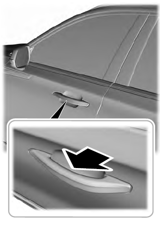
Electronic door handles are on each door. Gently depress the switch inside the exterior door handle to unlock and open the door. An unlock symbol illuminates on the door window trim indicating your vehicle is unlocked.

