Lincoln Aviator: Steering Wheel and Column Electrical Components / Removal and Installation - Steering Column Control Module (SCCM) - Vehicles With: Adaptive Steering
Removal
NOTE: Removal steps in this procedure may contain installation details.
NOTE: Make sure the road wheels are in the straight ahead position, regardless of steering wheel position.
-
NOTE: This step is only necessary when installing a new component.
NOTE: The PMI process must begin with the current SCCM installed. If the current SCCM does not respond to the diagnostic scan tool, the tool may prompt for As-Built Data as part of the repair.
Using a diagnostic scan tool, begin the PMI process for the SCCM following the on-screen instructions.
-
Remove the steering wheel.
Refer to: Steering Wheel - Vehicles With: Adaptive Steering (211-04 Steering Column, Removal and Installation).
-
Disconnect the SCCM electrical connectors and position aside the harness.
.jpg) |
-
Remove the retainers and the SCCM.
Torque: 35 lb.in (4 Nm)
.jpg) |
Installation
-
To install, reverse the removal procedure.
-
NOTE: This step is only necessary when installing a new component.
Using a diagnostic scan tool, complete the PMI process for the SCCM following the on-screen instructions.
 Removal and Installation - Steering Column Control Module (SCCM)
Removal
NOTE:
Removal steps in this procedure may contain installation details.
NOTE:
This step is only necessary when installing a new component...
 Removal and Installation - Steering Column Control Switch
Removal
NOTE:
Removal steps in this procedure may contain installation details.
Remove the steering column shrouds.
Refer to: Steering Column Shrouds (501-05 Interior Trim and Ornamentation, Removal and Installation)...
Other information:
Lincoln Aviator 2020-2025 Service Manual: General Procedures - Tire Pressure Monitoring System (TPMS) Sensor Activation
Special Tool(s) / General Equipment 204-D081A (204-D081) Tire Pressure Monitor (TPMS) Activation NOTE: The tire pressure sensors will go into a "sleep mode" when a vehicle is stationary to conserve battery power. The sensors do not transmit information while in sleep mode...
Lincoln Aviator 2020-2025 Owners Manual: Switching Intelligent Mode On and Off
WARNING: You are responsible for controlling your vehicle at all times. The system is designed to be an aid and does not relieve you of your responsibility to drive with due care and attention. Failure to follow this instruction could result in the loss of control of your vehicle, personal injury or death...
Categories
- Manuals Home
- Lincoln Aviator Owners Manual
- Lincoln Aviator Service Manual
- Keyless Entry
- Child Safety Locks
- Locking and Unlocking
- New on site
- Most important about car
Children and Airbags
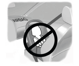
WARNING: Airbags can kill or injure a child in a child restraint. Never place a rear-facing child restraint in front of an active airbag. If you must use a forward-facing child restraint in the front seat, move the seat upon which the child restraint is installed all the way back.

