Lincoln Aviator 2020-2026 Service Manual / Powertrain / Automatic Transmission / Automatic Transmission - 10-Speed Automatic Transmission – 10R60 / Removal and Installation - Turbine Shaft Speed (TSS) Sensor
Lincoln Aviator: Automatic Transmission - 10-Speed Automatic Transmission – 10R60 / Removal and Installation - Turbine Shaft Speed (TSS) Sensor
Removal
-
Remove the main control valve body.
Refer to: Main Control Valve Body (307-01A Automatic Transmission - 10-Speed Automatic Transmission – 10R60, Removal and Installation).
-
Remove the TSS sensor.
-
Slide the plastic lock to the unlocked position.
While pressing the plastic tab, disconnect the electrical connector.
-
Remove the bolt and the TSS sensor.
-
Slide the plastic lock to the unlocked position.
While pressing the plastic tab, disconnect the electrical connector.
.jpg) |
Installation
-
Install the TSS sensor.
-
Install the TSS sensor bolt.
Torque: 62 lb.in (7 Nm)
-
Connect the electrical connector. Slide the plastic lock to the locked position.
-
Install the TSS sensor bolt.
.jpg) |
-
Install the main control valve body.
Refer to: Main Control Valve Body (307-01A Automatic Transmission - 10-Speed Automatic Transmission – 10R60, Removal and Installation).
 Removal and Installation - Transmission Support Insulator
Special Tool(s) /
General Equipment
Transmission Jack
Wooden Block
Removal
With the vehicle in NEUTRAL, position it on a hoist...
 Overhaul - Main Control Valve Body
Special Tool(s) /
General Equipment
307-299Alignment Pins, Valve BodyTKIT-1994-LMH/MH2TKIT-1994-FTKIT-1994-FLM/FM
Materials
Name
Specification
Motorcraft® MERCON® ULV Automatic Transmission FluidXT-12-QULV
WSS-M2C949-A, MERCON® ULV
For solenoid and valve identification...
Other information:
Lincoln Aviator 2020-2026 Service Manual: Removal and Installation - Rear Door Glass Run and Bracket
Removal NOTE: LH (left-hand) side shown, RH (right-hand) side similar. NOTE: Removal steps in this procedure may contain installation details. Aft rear door glass run and bracket Remove the rear door window regulator and motor. Refer to: Rear Door Window Regulator and Motor (501-11 Glass, Frames and Mechanisms, Removal and Installation)...
Lincoln Aviator 2020-2026 Service Manual: Description and Operation - Wheel and Tire Health and Safety Precautions
WARNING: Never inflate a tire that has been run flat without first removing the tire from the wheel to inspect for damage. A damaged tire can fail during inflation. Failure to follow this instruction may result in serious personal injury...
Categories
- Manuals Home
- Lincoln Aviator Owners Manual
- Lincoln Aviator Service Manual
- Configuring The Head Up Display
- Description and Operation - Body and Frame
- Body and Paint
- New on site
- Most important about car
Activating Intelligent Access
The intelligent access key must be within 3 ft (1 m) of the door or luggage compartment you intend to lock or unlock.
At a Door
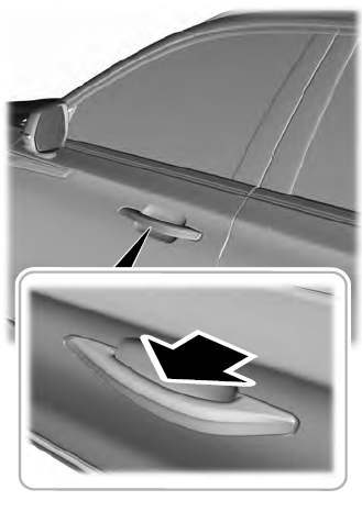
Electronic door handles are on each door. Gently depress the switch inside the exterior door handle to unlock and open the door. An unlock symbol illuminates on the door window trim indicating your vehicle is unlocked.

Copyright © 2026 www.liaviator2.com
