Lincoln Aviator: Maintenance / Adjusting the Headlamps
Vertical Aim Adjustment
If your vehicle has been involved in a crash,
have the aim of the headlamp beam checked
by an authorized dealer.

- 8 ft (2.4 m).
- Ground to the center of the
headlamp high beam bulb.
- 25 ft (7.6 m).
- Horizontal reference line.
Vertical Aim Adjustment Procedure
- Park your vehicle on level ground
approximately 25 ft (7.6 m) from a wall or
screen.
- Measure the distance from the ground
to the center of the headlamp high beam
bulb and mark an 8 ft (2.4 m) long
horizontal reference line on the wall or
screen at this height.
Note: There may be an identifying mark on
the lens to help you locate the center line of
the headlamp high beam bulb.
Note: To see a clearer light pattern for
adjusting, you may want to block the light
from one headlamp while adjusting the
other.
- Switch on the low beam headlamps and
open the hood.

- On the wall or screen you will observe a
flat zone of high intensity light located at
the top of the beam pattern. If the top
edge of the flat zone of high intensity
light is not on the horizontal reference
line, adjust the aim of the headlamp
beam.

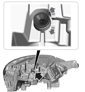
- Use a suitable tool, for example a
screwdriver or socket wrench, to turn the
adjuster clockwise or counterclockwise
to adjust the vertical aim of the
headlamp. The horizontal edge of the
brighter light should touch the horizontal
reference line.
- Close the hood and switch off the lamps.
To disconnect or remove the battery, do the
following:
Apply the parking brake and switch the
ignition off.
Switch all electrical equipment off, for
example lights and radio...
Washer Fluid Check
WARNING: If you operate your
vehicle in temperatures below 41.0°F (5°C),
use washer fluid with antifreeze protection.
Failure to use washer fluid with antifreeze
protection in cold weather could result in
impaired windshield vision and increase
the risk of injury or accident...
Other information:
Diagnostic Trouble Code (DTC) Chart
Diagnostics in this manual assume a certain skill level and knowledge of Ford-specific diagnostic practices. REFER to: Diagnostic Methods (100-00 General Information, Description and Operation).
Diagnostic Trouble Code Chart
Module
DTC
Description
Action
SUMA
B1041:52
Levelling Control: Not Activated
GO to Pinpoint Test W
SUMA
C1043:00
Pressure Decrease Too Slow From Reservoir: No Sub Type Information
GO to Pinpoint Test M
SUMA
C104C:11
Left Rear Spring Rate Valve: Circuit Short To Ground
GO to Pinpoint Test E
SUMA
C104C:12
Left Rear Spring Rate Valve: Circuit Short To Battery
GO to Pinpoint Test E
SUMA
C104C:13
Left Rear Spring Rate Valve: Circuit Open
GO to Pinpoint Test E
SUMA
C104C:1A
Left Rear Spring Rate Valve: Circuit Resistance Below Threshold
GO to Pinpoint Test E
SUMA
C104C:1F
Left Rear Spring Rate Valve: Circuit Intermittent
GO to Pinpoint Test E
SUMA
C104D:11
Right Front Spring Rate Valve: Circuit Short To Ground
GO to Pinpoint Test D
SUMA
C104D:12
Right Front Spring Rate Valve: Circuit Short To Battery
GO to Pinpoint Test D
SUMA
C104D:13
Right Front Spring Rate Valve: Circuit Open
GO to Pinpoint Test D
SUMA
C104D:1A
Right Front Spring Rate Valve: Circuit Resistance Below Threshold
GO to Pinpoint Test D
SUMA
C104D:1F
Right Front Spring Rate Valve: Circuit Intermittent
GO to Pinpoint Test D
SUMA
C104E:11
Right Rear Spring Rate Valve: Circuit Short To Ground
GO to Pinpoint Test F
SUMA
C104E:12
Right Rear Spring Rate Valve: Circuit Short To Battery
GO to Pinpoint Test F
SUMA
C104E:13
Right Rear Spring Rate Valve: Circuit Open
GO to Pinpoint Test F
SUMA
C104E:1A
Right Rear Spring Rate Valve: Circuit Resistance Below Threshold
GO to Pinpoint Test F
SUMA
C104E:1F
Right Rear Spring Rate Valve: Circuit Intermittent
GO to Pinpoint Test F
SUMA
C104F:11
Left Front Spring Rate Valve: Circuit Short To Ground
GO to Pinpoint Test C
SUMA
C104F:12
Left Front Spring Rate Valve: Circuit Short To Battery
GO to Pinpoint Test C
SUMA
C104F:13
Left Front Spring Rate Valve: Circuit Open
GO to Pinpoint Test C
SUMA
C104F:1A
Left Front Spring Rate Valve: Circuit Resistance Below Threshold
GO to Pinpoint Test C
SUMA
C104F:1F
Left Front Spring Rate Valve: Circuit Intermittent
GO to Pinpoint Test C
SUMA
C1124:07
Height Sensor(s): Mechanical Failures
GO to Pinpoint Test G
SUMA
C1124:11
Height Sensor(s): Circuit Short To Ground
GO to Pinpoint Test H
SUMA
C1124:12
Height Sensor(s): Circuit Short To Battery
GO to Pinpoint Test H
SUMA
C1124:54
Height Sensor(s): Missing Calibration
GO to Pinpoint Test U
SUMA
C1A03:2A
Left Front Height Sensor: Stuck in Range
GO to Pinpoint Test I
SUMA
C1A03:34
Left Front Height Sensor: Signal High Time Less Than Minimum
GO to Pinpoint Test I
SUMA
C1A03:35
Left Front Height Sensor: Signal High Time Greater Than Maximum
GO to Pinpoint Test I
SUMA
C1A03:36
Left Front Height Sensor: Signal Frequency Too Low
GO to Pinpoint Test I
SUMA
C1A03:37
Left Front Height Sensor: Signal Frequency Too High
GO to Pinpoint Test I
SUMA
C1A03:84
Left Front Height Sensor: Signal Below Allowable Range
GO to Pinpoint Test I
SUMA
C1A03:85
Left Front Height Sensor: Signal Above Allowable Range
GO to Pinpoint Test I
SUMA
C1A04:2A
Right Front Height Sensor: Stuck in Range
GO to Pinpoint Test J
SUMA
C1A04:34
Right Front Height Sensor: Signal High Time Less Than Minimum
GO to Pinpoint Test J
SUMA
C1A04:35
Right Front Height Sensor: Signal High Time Greater Than Maximum
GO to Pinpoint Test J
SUMA
C1A04:36
Right Front Height Sensor: Signal Frequency Too Low
GO to Pinpoint Test J
SUMA
C1A04:37
Right Front Height Sensor: Signal Frequency Too High
GO to Pinpoint Test J
SUMA
C1A04:84
Right Front Height Sensor: Signal Below Allowable Range
GO to Pinpoint Test J
SUMA
C1A04:85
Right Front Height Sensor: Signal Above Allowable Range
GO to Pinpoint Test J
SUMA
C1A05:2A
Left Rear Height Sensor: Stuck in Range
GO to Pinpoint Test K
SUMA
C1A05:34
Left Rear Height Sensor: Signal High Time Less Than Minimum
GO to Pinpoint Test K
SUMA
C1A05:35
Left Rear Height Sensor: Signal High Time Greater Than Maximum
GO to Pinpoint Test K
SUMA
C1A05:36
Left Rear Height Sensor: Signal Frequency Too Low
GO to Pinpoint Test K
SUMA
C1A05:37
Left Rear Height Sensor: Signal Frequency Too High
GO to Pinpoint Test K
SUMA
C1A05:84
Left Rear Height Sensor: Signal Below Allowable Range
GO to Pinpoint Test K
SUMA
C1A05:85
Left Rear Height Sensor: Signal Above Allowable Range
GO to Pinpoint Test K
SUMA
C1A06:2A
Right Rear Height Sensor: Stuck in Range
GO to Pinpoint Test L
SUMA
C1A06:34
Right Rear Height Sensor: Signal High Time Less Than Minimum
GO to Pinpoint Test L
SUMA
C1A06:35
Right Rear Height Sensor: Signal High Time Greater Than Maximum
GO to Pinpoint Test L
SUMA
C1A06:36
Right Rear Height Sensor: Signal Frequency Too Low
GO to Pinpoint Test L
SUMA
C1A06:37
Right Rear Height Sensor: Signal Frequency Too High
GO to Pinpoint Test L
SUMA
C1A06:84
Right Rear Height Sensor: Signal Below Allowable Range
GO to Pinpoint Test L
SUMA
C1A06:85
Right Rear Height Sensor: Signal Above Allowable Range
GO to Pinpoint Test L
SUMA
C1A20:00
Pressure Increase Too Slow When Filling Reservoir: No Sub Type Information
GO to Pinpoint Test M
SUMA
C1A27:09
Compressor: Component Failures
GO to Pinpoint Test N
SUMA
C1A27:63
Compressor: Circuit/Component Protection Time-Out
GO to Pinpoint Test N
SUMA
C1A27:98
Compressor: Component Or System Over Temperature
GO to Pinpoint Test N
SUMA
C1A27:99
Compressor: Exceeded Learning Limit
GO to Pinpoint Test N
SUMA
C1A31:63
Left Front Corner Valve: Circuit/Component Protection Time-Out
GO to Pinpoint Test AD
SUMA
C1A32:63
Right Front Corner Valve: Circuit/Component Protection Time-Out
GO to Pinpoint Test AD
SUMA
C1A33:63
Left Rear Corner Valve: Circuit/Component Protection Time-Out
GO to Pinpoint Test AD
SUMA
C1A34:63
Right Rear Corner Valve: Circuit/Component Protection Time-Out
GO to Pinpoint Test AD
SUMA
C1A36:63
Exhaust Valve: Circuit/Component Protection Time-Out
GO to Pinpoint Test AD
SUMA
U0100:87
Lost Communication With ECM / PCM: Missing Message
GO to Pinpoint Test O
SUMA
U0121:87
Lost Communication With Anti-Lock Brake System (ABS) Control Module: Missing Message
GO to Pinpoint Test P
SUMA
U0122:87
Lost Communication With Vehicle Dynamics Control Module: Missing Message
GO to Pinpoint Test Q
SUMA
U0131:87
Lost Communication With Power Steering Control Module "A": Missing Message
GO to Pinpoint Test R
SUMA
U0140:87
Lost Communication With Body Control Module: Missing Message
GO to Pinpoint Test S
SUMA
U0146:87
Lost Communication With Serial Data Gateway "A": Missing Message
GO to Pinpoint Test T
SUMA
U0401:00
Invalid Data Received from ECM/PCM A: No Sub Type Information
GO to Pinpoint Test X
SUMA
U0415:00
Invalid Data Received from Anti-Lock Brake System (ABS) Control Module "A": No Sub Type Information
GO to Pinpoint Test Y
SUMA
U0416:00
Invalid Data Received From Vehicle Dynamics Control Module: No Sub Type Information
GO to Pinpoint Test Z
SUMA
U0420:00
Invalid Data Received from Power Steering Control Module "A": No Sub Type Information
GO to Pinpoint Test AA
SUMA
U0422:00
Invalid Data Received From Body Control Module: No Sub Type Information
GO to Pinpoint Test AB
SUMA
U0447:00
Invalid Data Received From Serial Data Gateway "A": No Sub Type Information
GO to Pinpoint Test AC
SUMA
U2100:00
Initial Configuration Not Complete: No Sub Type Information
GO to Pinpoint Test V
SUMA
U2100:56
Initial Configuration Not Complete: Invalid/Incompatible Configuration
GO to Pinpoint Test V
SUMA
U3000:04
Control Module: System Internal Failures
GO to Pinpoint Test V
SUMA
U3000:45
Control Module: Program Memory Failure
GO to Pinpoint Test V
SUMA
U3000:46
Control Module: Calibration/Parameter Memory Failure
GO to Pinpoint Test V
SUMA
U3000:47
Control Module: Watchdog/Safety µC Failure
GO to Pinpoint Test V
SUMA
U3000:48
Control Module: Supervision Software Failure
GO to Pinpoint Test V
SUMA
U3003:16
Battery Voltage: Circuit Voltage Below Threshold
GO to Pinpoint Test A
SUMA
U3003:17
Battery Voltage: Circuit Voltage Above Threshold
GO to Pinpoint Test B
Symptom Chart
Symptom Chart: Vehicle Dynamic Suspension
Diagnostics
in this manual assume a certain skill level and knowledge of
Ford-specific diagnostic practices...
Removal
NOTE:
Removal steps in this procedure may contain installation details.
NOTE:
If installing a new module, it is necessary to
upload the module configuration information to the diagnostic scan tool
prior to removing the module. This information must be downloaded into
the new module after installation...