Lincoln Aviator 2020-2026 Service Manual / Chassis / Brake System / Anti-Lock Brake System (ABS) and Stability Control
Lincoln Aviator: Brake System / Anti-Lock Brake System (ABS) and Stability Control
- Description and Operation - Anti-Lock Brake System (ABS) and Stability Control - Overview
- Description and Operation - Anti-Lock Brake System (ABS) and Stability Control - System Operation and Component Description
- Removal and Installation - Electric Brake Booster (EBB)
- Removal and Installation - Front Wheel Speed Sensor
- Removal and Installation - Rear Wheel Speed Sensor
 Description and Operation - Power Brake System - System Operation and Component Description
System Operation
System Diagram - Electric Brake Boost
E347819
*.sttxt {
visibility: hidden;
}
*.stcallout {
visibility: visible;
}
HS-CAN3
HS-CAN1
HS-CAN2
1
IPC
2
RCM
3
BCM
4
PCM
5
GWM
6
ABS/EBB
7
Wheel speed
sensors
8
Brake pedal
Item
Description
1
IPC
2
RCM
3
BCM
4
PCM
5
GWM
6
ABS/ EBB
7
Wheel speed sensors
8
Brake pedal
Network Message Chart
Module Network Input Messages - ABS Module
Broadcast Message
Originating Module
Message Purpose
Accelerator pedal position
PCM
This message is first sent to the GWM and then to the ABS module...
 Description and Operation - Anti-Lock Brake System (ABS) and Stability Control - Overview
Overview
The ABS
and stability control systems are comprised of the following subsystems
to assist the driver in maintaining control of the vehicle:
ABS
Curve control
Drive away release (EPB)
EBD
EPB control
ESC
Hill descent control
Hill start assist
Hydraulic fade compensation
RSC
Selectable drive modes
Supplemental braking assist
Supports adaptive cruise control
Supports collision avoidance
Traction control
Trailer sway control
The ABS helps maintain steering control during hard braking by preventing wheel lockup...
Other information:
Lincoln Aviator 2020-2026 Service Manual: Removal and Installation - Overhead Speaker
Removal NOTE: Removal steps in this procedure may contain installation details. NOTE: LH front speaker is shown, all others are similar. Lower the headliner. Refer to: Headliner - Lowering (501-05 Interior Trim and Ornamentation, Removal and Installation)...
Lincoln Aviator 2020-2026 Service Manual: Removal - Engine Block Skirt Stiffener
Special Tool(s) / General Equipment 205-153 (T80T-4000-W) Handle 303-1246Engine Spreader BarTKIT-2006UF-FLMTKIT-2006UF-ROW 303-1247VCT Spark Plug Tube Seal Remover and InstallerTKIT-2006UF-FLMTKIT-2006UF-ROW 303-1634Lift Eyes (2)TKIT-2014D-ROW3TKIT-2014D-FL_ROW 303-409 (T92C-6700-CH) Remover, Crankshaft SealTKIT-1992-FH/FMH/FLMHTKIT-1993-LMH/MH Floor Crane Mounting Stand Plastic Scraper Flat-Bladed Screwdriver Materials Name Specification Motorcraft® Silicone Gasket RemoverZC-30-A - Motorcraft® Metal Surface Prep WipesZC-31-B - Motorcraft® Metal Brake Parts CleanerPM-4-A, PM-4-B - NOTICE: During engine repair procedures, cleanliness is extremely important...
Categories
- Manuals Home
- Lincoln Aviator Owners Manual
- Lincoln Aviator Service Manual
- Drive Modes
- Description and Operation - Jacking and Lifting
- Resetting the System
- New on site
- Most important about car
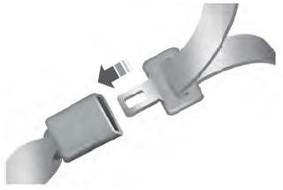
Fastening the Seatbelts
The front outboard and rear safety restraints in the vehicle are combination lap and shoulder belts.
Insert the belt tongue into the proper buckle (the buckle closest to the direction the tongue is coming from) until you hear a snap and feel it latch. Make sure that you securely fasten the tongue in the buckle.
Copyright © 2026 www.liaviator2.com
