
Lincoln Aviator: Anti-Lock Brake System (ABS) and Stability Control / Removal and Installation - Front Wheel Speed Sensor
Materials
| Name | Specification |
|---|---|
| Motorcraft® Metal Brake Parts Cleaner PM-4-A, PM-4-B |
- |
Removal
NOTE: Removal steps in this procedure may contain installation details.
-
Remove the wheel and tire.
Refer to: Wheel and Tire (204-04A Wheels and Tires, Removal and Installation).
-
Disconnect the electrical connector.
.jpg) |
-
NOTICE: Route the wheel speed sensor harness as shown or contact with the wheel may occur causing damage to the harness.
Detach the wiring retainers.
.jpg) |
-
NOTE: Make sure that the sensor housing area is clean and free of foreign material before the sensor is removed.
Using compressed air, clean the sensor housing area.
.jpg) |
-
Detach the wiring retainer, remove the bolt and the front wheel speed sensor
Torque: 106 lb.in (12 Nm)
.jpg) |
Installation
-
NOTICE: Before installing a new sensor, inspect the sensor housing to make sure the sensor cavity is clean and free of foreign material or damage to the sensor may occur.
Clean and inspect the sensor housing cavity.
Material: Motorcraft® Metal Brake Parts Cleaner / PM-4-A, PM-4-B
.jpg) |
-
To install, reverse the removal procedure.
 Removal and Installation - Electric Brake Booster (EBB)
Removal
NOTE:
Removal steps in this procedure may contain installation details.
NOTE:
The EBB and the ABS module are serviced as an assembly and should not be separated...
 Removal and Installation - Rear Wheel Speed Sensor
Materials
Name
Specification
Motorcraft® Metal Brake Parts CleanerPM-4-A, PM-4-B
-
Removal
NOTE:
Removal steps in this procedure may contain installation details...
Other information:
Lincoln Aviator 2020-2026 Owners Manual: Switching Off Your Vehicle When It Is Moving
WARNING: Switching off the engine when your vehicle is still moving results in a significant decrease in braking assistance. Higher effort is required to apply the brakes and to stop your vehicle. A significant decrease in steering assistance could also occur...
Lincoln Aviator 2020-2026 Service Manual: Removal and Installation - Fuel Tank Filler Pipe
Removal NOTE: Removal steps in this procedure may contain installation steps. Disconnect the battery. Refer to: Battery Disconnect and Connect (414-01 Battery, Mounting and Cables, General Procedures). With the vehicle in NEUTRAL, position it on a hoist...
Categories
- Manuals Home
- Lincoln Aviator Owners Manual
- Lincoln Aviator Service Manual
- Opening and Closing the Hood
- Tire Change Procedure
- Keyless Entry
- New on site
- Most important about car
Child Seats
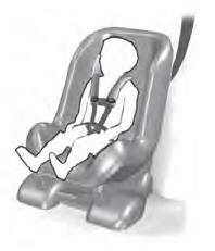
Use a child restraint (sometimes called an infant carrier, convertible seat, or toddler seat) for infants, toddlers and children weighing 40 lb (18 kg) or less (generally four-years-old or younger).
Using Lap and Shoulder Belts
WARNING: Do not place a rearward facing child restraint in front of an active airbag. Failure to follow this instruction could result in personal injury or death.
