
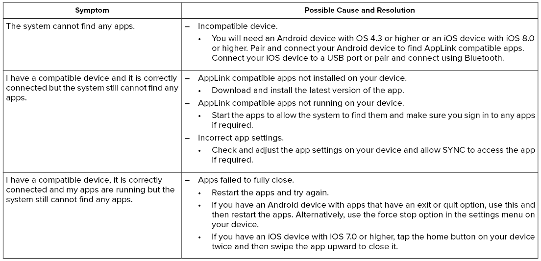
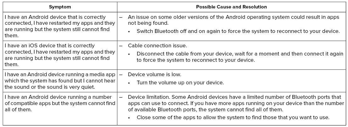
Lincoln Aviator: SYNC™ 3 Troubleshooting / Apps


Other information:
Lincoln Aviator 2020-2026 Service Manual: Removal and Installation - Windshield Washer Reservoir
Special Tool(s) / General Equipment Fluid Suction Gun Fluid Container Materials Name Specification Motorcraft® Premium Windshield Wash Concentrate with BitterantZC-32-B2 WSS-M14P19-A Removal NOTE: Removal steps in this procedure may contain installation details...
Lincoln Aviator 2020-2026 Service Manual: Removal and Installation - C-Pillar Side Impact Sensor
Removal WARNING: The following procedure prescribes critical repair steps required for correct restraint system operation during a crash. Follow all notes and steps carefully. Failure to follow step instructions may result in incorrect operation of the restraint system and increases the risk of serious personal injury or death in a crash...
Categories
- Manuals Home
- Lincoln Aviator Owners Manual
- Lincoln Aviator Service Manual
- General Procedures - Transmission Fluid Drain and Refill
- Garage Door Opener
- USB Port and Power Point Locations
- New on site
- Most important about car
Activating Intelligent Access
The intelligent access key must be within 3 ft (1 m) of the door or luggage compartment you intend to lock or unlock.
At a Door
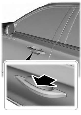
Electronic door handles are on each door. Gently depress the switch inside the exterior door handle to unlock and open the door. An unlock symbol illuminates on the door window trim indicating your vehicle is unlocked.

Copyright © 2026 www.liaviator2.com