Lincoln Aviator: Climate Control System - General Information / Removal and Installation - Condenser Inlet Line - 3.0L EcoBoost
Removal
NOTICE: During the removal of components, cap, tape or otherwise appropriately protect all openings to prevent the ingress of dirt or other contamination. Remove protective materials prior to installation.
NOTE: Removal steps in this procedure may contain installation details.
-
Recover the refrigerant. Refer to the appropriate Recovery procedure in Group 412.
-
Remove the horn.
Refer to: Horn (413-06 Horn, Removal and Installation).
-
NOTE: The condenser inlet and outlet lines are replaced as an assembly.
-
Remove the condenser outlet line nut.
Torque: 71 lb.in (8 Nm)
-
Remove the condenser inlet line nut.
Torque: 133 lb.in (15 Nm)
-
Make sure to cover any open ports to prevent debris from entering the system.
-
Remove the condenser outlet line nut.
.jpg) |
-
Remove the PCM.
Refer to: Powertrain Control Module (PCM) (303-14A Electronic Engine Controls - 3.0L EcoBoost/3.0L EcoBoost – Hybrid (BQ), Removal and Installation).
-
Disconnect the harness retainers. Remove the bolts and the PCM mounting bracket.
Torque: 55 lb.in (6.2 Nm)
.jpg) |
-
-
Remove the condenser outlet line retainer.
Torque: 71 lb.in (8 Nm)
-
Remove the A/C compressor outlet line retainer and remove the condenser outlet and inlet line assembly.
Torque: 159 lb.in (18 Nm)
-
Make sure to cover any open ports to prevent debris from entering the system.
-
Remove the condenser outlet line retainer.
.jpg) |
Installation
-
To install, reverse the removal procedure.
-
NOTICE: Only use the specified material to lubricate the seals.
Install and lubricate new O-ring seals. Refer to the appropriate Specifications in Group 412.
-
Lubricate the refrigerant system with the correct amount
of clean PAG oil. Refer to the appropriate Refrigerant Oil Adding
procedure in Group 412.
 Removal and Installation - Condenser - 3.0L EcoBoost
Removal
NOTICE:
During the removal of components, cap, tape or otherwise
appropriately protect all openings to prevent the ingress of dirt or
other contamination...
 Removal and Installation - Condenser Outlet Line - 3.0L EcoBoost
Removal
NOTE:
The condenser inlet and outlet line are installed as a one-piece assembly.
Remove the condenser inlet line.
Refer to: Condenser Inlet Line - 3...
Other information:
Lincoln Aviator 2020-2026 Owners Manual: Emergency Call Requirements. Emergency Call Limitations
Emergency Call Requirements WARNING: Do not wait for 911 Assist to make an emergency call if you can do it yourself. Dial emergency services immediately to avoid delayed response time which could increase the risk of serious injury or death after a crash...
Lincoln Aviator 2020-2026 Service Manual: Description and Operation - Transmission Description - Overview
Overview The 10R60 automatic transmission is a 10-speed electronically controlled transmission with a main control valve body unit with 8 solenoids and a torque converter. Gear selection is achieved by the control of transmission fluid to operate various internal clutches...
Categories
- Manuals Home
- Lincoln Aviator Owners Manual
- Lincoln Aviator Service Manual
- USB Port and Power Point Locations
- Disabling Auto-Start-Stop
- Body and Paint
- New on site
- Most important about car
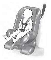
Child Seats

Use a child restraint (sometimes called an infant carrier, convertible seat, or toddler seat) for infants, toddlers and children weighing 40 lb (18 kg) or less (generally four-years-old or younger).
Using Lap and Shoulder Belts
WARNING: Do not place a rearward facing child restraint in front of an active airbag. Failure to follow this instruction could result in personal injury or death.
