Lincoln Aviator: Engine - 3.0L EcoBoost / Assembly - Engine
Special Tool(s) /
General Equipment
.jpg) |
205-153
(T80T-4000-W)
Handle |
 |
303-1246
Engine Spreader Bar
TKIT-2006UF-FLM
TKIT-2006UF-ROW |
 |
303-1247
VCT Spark Plug Tube Seal Remover and Installer
TKIT-2006UF-FLM
TKIT-2006UF-ROW |
.jpg) |
303-1248
Camshaft holding tools
TKIT-2006UF-FLM
TKIT-2006UF-ROW |
.jpg) |
303-1250
Seal Installer, Rear Main
TKIT-2006UFFLM |
 |
303-1531
Installer, Front Crank Seal and Damper |
.jpg) |
303-1633
Remover, Roller Rocker Follower
TKIT-2014D-ROW3
TKIT-2014D-FL_ROW |
.jpg) |
303-1634
Lift Eyes (2)
TKIT-2014D-ROW3
TKIT-2014D-FL_ROW |
.jpg) |
303-1696
Camshaft holding fixture |
.jpg) |
303-335
(T88T-6701-A)
Installer, Front Cover Oil Seal
TKIT-1988-FLM
TKIT-1988-F |
| Floor Crane |
| Mounting Stand |
| Plastic Scraper |
| Flat-Bladed Screwdriver |
| Piston Ring Compressor |
| Vise |
| Vise Jaw Protectors |
Materials
| Name |
Specification |
Motorcraft® High Performance Engine RTV Silicone
TA-357 |
WSE-M4G323-A6
|
Motorcraft® Silicone Gasket Remover
ZC-30-A |
-
|
Flange Sealant
CU7Z-19B508-A |
WSS-M2G348-A11
|
Motorcraft® Metal Surface Prep Wipes
ZC-31-B |
-
|
Motorcraft® Metal Brake Parts Cleaner
PM-4-A, PM-4-B |
-
|
NOTICE:
During engine repair procedures, cleanliness is extremely
important. Any foreign material, including any material created while
cleaning gasket surfaces, that enters the oil passages, coolant passages
or the oil pan, can cause engine failure.
NOTICE:
The turbocharger compressor vanes can be damaged by even the
smallest particles. When removing any turbocharger or engine air intake
system component, ensure that no debris enters the system. Failure to do
so may result in damage to the turbocharger.
NOTE:
If the components are to be reinstalled, they must be installed
in their original location. Mark the components for installation into
their original location.
NOTE:
Refer to the exploded view under the Engine Component View in the Description and Operation.
LHD AWD/LHD RWD
-
Inspect the turbocharger or engine air intake system components and clean, if necessary.
-
Read and record the four character code on the cylinder
block. The first letter is the code for main No. 1, the second letter
for main No. 2, the third letter for main No. 3 and the fourth letter
for main No. 4.
-
Read and record the four character code on the
crankshaft face. The first letter is the code for main No. 1, the second
letter for main No. 2, the third letter for main No. 3 and the fourth
letter for main No. 4.
.jpg) |
|
-
Using the data recorded earlier and the Bearing Select
Fit Chart, determine the required bearing grade for the main bearings.
-
Look at the bearing select fit chart and for each
main, match the block and crankshaft code with its corresponding column
or row by reading across the crankshaft row and down the block column to
select the proper grade bearings for each main.
-
For example, if the block code is GLMD and the
crankshaft code is PNLO, main No. 1 should be assembled with grade 2
upper and lower bearings, as determined by the intersection of the G block column and the P
crankshaft row. Main No. 2 should be assembled with grade 3 upper and
lower bearings. Main No. 3 should be assembled with grade 3 upper and
grade 4 lower bearings. Main No. 4 should be assembled with grade 2
upper and lower bearings.
-
Install the piston cooling jets and bolts into the cylinder block.
Torque:
89 lb.in (10 Nm)
-
Install the crankshaft main bearings.
-
Install the crankshaft upper main bearings and thrust bearing into the cylinder block.
-
Install the crankshaft lower main bearings into the bearing caps.
-
Make sure all oil passages are aligned.
-
Lubricate all main bearings with clean engine oil.
-
-
Lubricate the crankshaft bearing journals with clean engine oil.
-
Install the crankshaft into the cylinder block.
-
Install the No. 1, 2 and 3 main bearing caps and bolts
on the cylinder block and, keeping the caps as square as possible,
alternately draw the caps down evenly using the cap bolts.
-
-
Lubricate the lower thrust washer with clean engine oil.
-
Install the lower thrust washer and the No. 4 main
bearing cap and, keeping the cap as square as possible, alternately draw
the cap down evenly using the cap bolts.
-
Push the crankshaft forward to seat the crankshaft thrust washer.
-
Tighten the main bearing cap bolts.
Torque:
Stage 1:
30 lb.ft (40 Nm)
Stage 2:
Loosen: 360°
Stage 3:
26 lb.ft (35 Nm)
Stage 4:
180°
-
-
Check the crankshaft end play.
Refer to: Specifications (303-01A Engine - 3.0L EcoBoost, Specifications).
-
Check the piston-to-cylinder block and piston ring clearances.
Refer to: Specifications (303-01A Engine - 3.0L EcoBoost, Specifications).
-
Assemble the pistons and position the piston ring gaps.
Refer to: Piston (303-01A Engine - 3.0L EcoBoost, Disassembly and Assembly of Subassemblies).
-
Lubricate with clean engine oil and install the connecting rod bearings.
-
-
For assembly purposes the bump on the connecting rod
will face the same way as the bump on the connecting rod cap.
-
-
For assembly purposes the bowl on the dome of the piston should be facing toward the intake of the engine.
-
On the RH bank the bump on the connecting rod should face the front of the engine.
-
On the LH bank the bump on the connecting rod should face the rear of the engine.
-
NOTICE:
Do not scratch the cylinder walls or crankshaft
journals with the connecting rod or engine damage may occur.
NOTICE:
Do not allow the piston connecting rods to come in
contact with the piston cooling jets or engine damage may occur.
-
Lubricate the piston with clean engine oil.
-
Position the piston assembly and piston ring installer into the cylinder.
Use the General Equipment: Piston Ring Compressor
-
Push the piston into the cylinder bore and guide the connecting rod onto the crankshaft journal.
.jpg) |
|
-
NOTICE:
The rod cap installation must keep the same
orientation as marked during disassembly or engine damage may occur.
NOTE:
The connecting rod caps are of the "cracked" design
and must mate with the connecting rod ends. Excessive bearing clearance
will result if not mated correctly.
-
Install the connecting rod cap and bearing.
Torque:
Stage 1:
24 lb.ft (32 Nm)
Stage 2:
Loosen: 180°
Stage 3:
24 lb.ft (32 Nm)
Stage 4:
90°
-
Repeat the steps for each of the remaining pistons.
-
Install the main bearing cap support braces and the bolts.
Torque:
Stage 1:
18 lb.ft (24 Nm)
Stage 2:
Loosen: 360°
Stage 3:
22 lb.ft (30 Nm)
Stage 4:
40°
-
NOTICE:
If the engine block skirt stiffener is not
installed, aligned and the bolts tightened to minimum specification
within 10 minutes, the sealant must be removed and the sealing area
cleaned.
Apply a 3.5 mm (0.14 in) bead of Motorcraft® High
Performance Engine RTV Silicone to the chamfer of the engine block skirt
stiffener.
Material: Motorcraft® High Performance Engine RTV Silicone
/ TA-357
(WSE-M4G323-A6)
-
-
Position the oil seal.
-
Install the engine block skirt stiffener.
-
-
Install the bolts finger tight.
-
Tighten the 2 bolts.
Torque:
Stage 1:
35 lb.in (4 Nm)
Stage 2:
Loosen: 360°
-
-
Using a straight edge, align the rear face of the
engine block skirt stiffener to the rear face of the engine block, flush
or up to 0.250 mm (0.01 in) underflush.
-
Using a straight edge, align the machined boss on
the left side of the engine block skirt stiffener to the machined boss
on the left side of the engine block flush or within 0.280 mm (0.011 in)
of flush.
-
NOTICE:
If the engine block skirt stiffener bolts minimal
torque is not completed within 10 minutes of sealant application, or if
final torque is not met within 60 minutes of sealant application the
parts must be removed and the sealant must be removed and the sealing
area cleaned.
Tighten the engine block skirt stiffener bolts.
Torque:
Stage 1:
35 lb.in (4 Nm)
Stage 2:
18 lb.ft (24 Nm)
-
NOTE:
Do not reuse the ECT sensor, install a new sensor.
Install a new ECT sensor.
Torque:
20 lb.ft (27 Nm)
-
-
Install the KS assembly and the bolts.
Torque:
97 lb.in (11 Nm)
-
Connect the ECT sensor electrical connector.
-
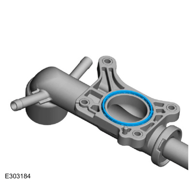
Install a new coolant outlet connector pipe gasket.
-
-
Install the coolant outlet connector pipe, the bolts and the stud bolt.
Torque:
89 lb.in (10 Nm)
-
Attach the wiring harness retainer to the stud bolt.
-
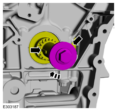
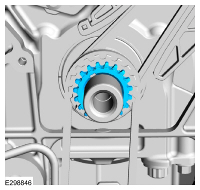
NOTE:
A timing mark is stamped on both faces of the
crankshaft sprocket. The sprocket can be installed with either of the
faces positioned outward.
Install the timing chain sprocket.
-
NOTICE:
Rotate the crankshaft utilizing only the original
crankshaft pulley bolt. Failure to follow this direction may cause
damage to the crankshaft and result in engine failure.
Install the original crankshaft pulley bolt and rotate
the crankshaft clockwise until the keyway is at the 9 o'clock position.
-
Install a new LH cylinder head gasket.
-
-
Install the cylinder head.
-
Install new cylinder head bolts.
Torque:
Stage 1:
177 lb.in (20 Nm)
Stage 2:
Loosen: 2 turn(s)
Stage 3:
37 lb.ft (50 Nm)
Stage 4:
180°
-
NOTICE:
Do not install the camshaft roller followers
at this time. The roller followers will be installed later in the
procedure. If the roller followers are installed prior to the camshafts,
the camshaft caps can become distorted during the camshaft tightening
process and result in upper end engine noise or severe damage to the
engine.
NOTE:
If the original hydraulic lash adjusters are to be
reinstalled, they must be installed in their original locations.
-
Lubricate the hydraulic lash adjusters with clean engine oil.
-
Install the hydraulic lash adjusters.
-
-
Lubricate the camshafts with clean engine oil.
-
Install the intake and exhaust camshafts in the
neutral position. Align the D-slots as shown in the illustration.
-
Install the camshaft bearing caps and the bolts. Do not tighten at this time.
-
Install the front camshaft bearing mega cap and the bolts. Do not tighten at this time.
-
Tighten the bolts.
Torque:
89 lb.in (10 Nm)
-
NOTICE:
The VCT units have 2 timing marks on them, a triangle and a circle. For installation of the LH side the circle marks are used.
-
Install the VCT units. The circle timing marks on the VCT units will be at the 10 o'clock (intake) and 12:30 (exhaust) positions as shown in the illustration.
Install Special Service Tool: 303-1248
Camshaft holding tools.
-
Install the new VCT unit bolts.
Torque:
Stage 1:
30 lb.ft (40 Nm)
Stage 2:
Loosen:
360°
Stage 3:
37 lb.ft (50 Nm)
Stage 4:
90°
-
Remove Special Service Tool: 303-1248
Camshaft holding tools.
-
Install a new RH cylinder head gasket.
-
-
Install the cylinder head.
-
Install new cylinder head bolts.
Torque:
Stage 1:
177 lb.in (20 Nm)
Stage 2:
Loosen: 2 turn(s)
Stage 3:
37 lb.ft (50 Nm)
Stage 4:
180°
-
NOTICE:
Do not install the camshaft roller followers
at this time. The roller followers will be installed later in the
procedure. If the roller followers are installed prior to the camshafts,
the camshaft caps can become distorted during the camshaft tightening
process and result in upper end engine noise or severe damage to the
engine.
NOTE:
If the original components are to be reinstalled, they must be installed in their original locations.
-
Lubricate the hydraulic lash adjusters with clean engine oil.
-
Install the hydraulic lash adjusters.
-
-
Lubricate the camshafts with clean engine oil.
-
Install the intake and exhaust camshafts in the
neutral position. Align the D-slots as shown in the illustration.
-
Apply a 1 mm bead of sealant to the rear camshaft cap mounting surface of the cylinder head.
Material: Flange Sealant
/ CU7Z-19B508-A
(WSS-M2G348-A11)
-
Install the camshaft bearing caps and the bolts. Do not tighten at this time.
-
Install the front camshaft bearing mega cap and the bolts. Do not tighten at this time.
-
Tighten the bolts.
Torque:
89 lb.in (10 Nm)
-
NOTICE:
The VCT units have 2 timing marks on them, a triangle and a circle. For installation of the RH side the triangle marks are used.
-
Install Special Service Tool: 303-1696
Camshaft holding fixture.
-
Install the VCT units. The triangle timing marks on the VCT units will be at the 2 o'clock (intake) and 11 o'clock (exhaust) positions as shown in the illustration.
-
Install the new VCT unit bolts.
Torque:
Stage 1:
30 lb.ft (40 Nm)
Stage 2:
Loosen:
360°
Stage 3:
37 lb.ft (50 Nm)
Stage 4:
90°
-
Remove Special Service Tool: 303-1696
Camshaft holding fixture.
-
Using the original crankshaft pulley bolt, rotate the
crankshaft clockwise until the keyway is at the 11 o'clock position.
-
NOTICE:
The VCT units have 2 timing marks on them, a triangle and a circle. For removal and installation of the LH side the circle marks are used.
-
Install the LH timing chain with the single colored links aligned with the circle timing marks on the VCT units.
-
Install the double colored links so they straddle the timing mark on the crankshaft sprocket.
-
Install the LH timing chain guide and bolts.
Torque:
89 lb.in (10 Nm)
-
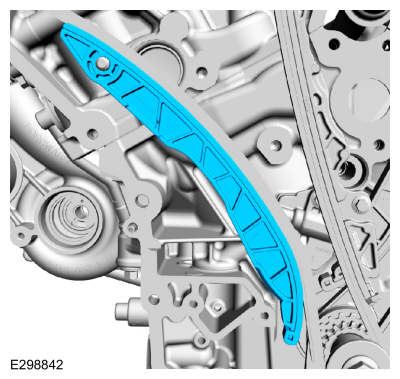
Install the LH timing chain tensioner arm.
-
Slide the tensioner cylinder out of the LH timing chain tensioner housing.
-
NOTICE:
Use vise jaw protectors or cover the jaws of the
vise with clean shop towels to prevent damage to the surface of the
tensioner ratchet mechanism.
Mount the flat machined surfaces on the end of the tensioner cylinder into a vise.
-
Using a flat-bladed screwdriver apply light downward pressure on the end of the tensioner ratchet mechanism.
Use the General Equipment: Vise
Use the General Equipment: Vise Jaw Protectors
Use the General Equipment: Flat-Bladed Screwdriver
-
Rotate the screwdriver clockwise approximately one turn.
-
An audible click will be heard when the tensioner ratchet mechanism locks into place.
-
Slide the tensioner cylinder into the tensioner housing
until it contacts the bottom of the bore. The shoulder of the tensioner
cylinder will be flush with the top of the housing.
-
-
Firmly press the tensioner cylinder into the
tensioner housing until the shoulder of the tensioner cylinder is
approximately 3 mm (0.125 in) below the top of the housing.
-
Install a retaining pin into the hole in the housing
to lock the tensioner cylinder in the retracted position.
-
-
Position the LH timing chain tensioner with the end of the tensioner correctly engaged to the tensioner arm.
-
Install the bolts.
Torque:
89 lb.in (10 Nm)
-
Remove the pin to allow the tensioner cylinder to extend and press against the timing chain tensioner arm.
-
NOTICE:
The crankshaft must be rotated clockwise one
revolution (360 degrees). Failure to do so will result in incorrect
camshaft timing.
-
Rotate the crankshaft clockwise one revolution (360 degrees).
-
Position the crankshaft sprocket keyway at the 11 o'clock position.
-
Remove and discard the original crankshaft pulley bolt.
-
Install the crankshaft sprocket.
-
Install the oil pump drive belt onto the crankshaft sprocket.
-
Prime the oil pump. Add 2 tablespoons of clean engine oil to the oil pump and rotate the oil pump by hand.
-
NOTE:
Make sure the oil pump drive belt teeth are engaged
in the crankshaft sprocket prior to installing the oil pump.
-
Install the oil pump sprocket into the oil pump drive belt.
-
Raise the rear of the oil pump assembly into the installed position.
-
Install the oil pump bolts.
Torque:
Stage 1:
89 lb.in (10 Nm)
Stage 2:
45°
-
-
Install new O-ring seals.
-
Lubricate the O-ring seals with clean engine oil.
-
-
Install the oil return tube and the bolts.
Torque:
89 lb.in (10 Nm)
-
Install the oil control solenoid and the bolt.
Torque:
89 lb.in (10 Nm)
-
Install the splash shield and the bolts.
Torque:
89 lb.in (10 Nm)
-
Install the timing chain sprocket.
-
NOTICE:
The VCT units have 2 timing marks on them, a triangle and a circle. For removal and installation of the RH side the triangle marks are used.
-
Install the RH timing chain with the single colored links aligned with the triangle timing marks on the VCT units.
-
Install the double colored links so they straddle the timing mark on the crankshaft sprocket.
-
Install the RH timing chain guide and bolts.
Torque:
89 lb.in (10 Nm)
-
Install the RH timing chain tensioner arm.
-
Slide the tensioner cylinder out of the RH timing chain tensioner housing.
-
NOTICE:
Use vise jaw protectors or cover the jaws of the
vise with clean shop towels to prevent damage to the surface of the
tensioner ratchet mechanism.
Mount the flat machined surfaces on the end of the tensioner cylinder into a vise.
-
Using a flat-bladed screwdriver apply light downward pressure on the end of the tensioner ratchet mechanism.
Use the General Equipment: Vise
Use the General Equipment: Vise Jaw Protectors
Use the General Equipment: Flat-Bladed Screwdriver
-
Rotate the screwdriver clockwise approximately one turn.
-
An audible click will be heard when the tensioner ratchet mechanism locks into place.
-
Slide the tensioner cylinder into the tensioner housing
until it contacts the bottom of the bore. The shoulder of the tensioner
cylinder will be flush with the top of the housing.
-
-
Firmly press the tensioner cylinder into the
tensioner housing until the shoulder of the tensioner cylinder is
approximately 3 mm (0.125 in) below the top of the housing.
-
Install a retaining pin into the hole in the housing
to lock the tensioner cylinder in the retracted position.
-
-
Position the RH timing chain tensioner with the end of the tensioner correctly engaged to the tensioner arm.
-
Install the bolts.
Torque:
89 lb.in (10 Nm)
-
Remove the pin to allow the tensioner cylinder to extend and press against the timing chain tensioner arm.
-
Install new engine front cover gaskets.
-
-
Lubricate a new oil gallery seal (6G068) with clean engine oil.
-
Install the new oil gallery seal (6G068).
-
NOTICE:
Failure to use Motorcraft® High Performance Engine
RTV Silicone may cause the engine oil to foam excessively and result in
serious engine damage.
NOTE:
The engine front cover must be installed within 10
minutes of applying the sealer and the bolts must be installed and
tightened to 2-5 Nm (18-44 lb-in) within 15 of applying the sealer.
Final tightening of the bolts must be completed within 60 minutes of
applying the sealer. Failure to follow this procedure can cause future
oil leakage.
Apply 9 mm (0.35 in) beads of Motorcraft® High
Performance Engine RTV Silicone 10 mm (0.40 in) in length to the
cylinder block skirt-to-cylinder block joints and the cylinder
head-to-cylinder block joints as indicated.
Material: Motorcraft® High Performance Engine RTV Silicone
/ TA-357
(WSE-M4G323-A6)
.jpg) |
|
-
NOTICE:
Failure to use Motorcraft® High Performance Engine
RTV Silicone may cause the engine oil to foam excessively and result in
serious engine damage.
NOTE:
The engine front cover must be installed within 10
minutes of applying the sealer and the bolts must be installed and
tightened to 2-5 Nm (18-44 lb-in) within 15 of applying the sealer.
Final tightening of the bolts must be completed within 60 minutes of
applying the sealer. Failure to follow this procedure can cause future
oil leakage.
-
Apply a 4.5 mm (0.18 in) bead of Motorcraft® High
Performance Engine RTV Silicone to the engine front cover sealing
surfaces of the inner bolt bosses.
Material: Motorcraft® High Performance Engine RTV Silicone
/ TA-357
(WSE-M4G323-A6)
-
Apply a 4.5 mm (0.18 in) bead of Motorcraft® High
Performance Engine RTV Silicone to the chamfer of the engine front cover
sealing surfaces.
Material: Motorcraft® High Performance Engine RTV Silicone
/ TA-357
(WSE-M4G323-A6)
.jpg) |
|
-
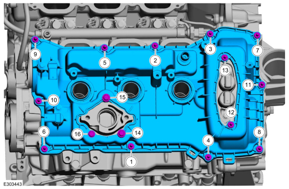
Install the engine front cover and the fasteners.
Torque:
Stage 1:
Tighten bolts 1 through 11 to:
18 lb.ft (24 Nm)
Stage 2:
Tighten bolts 12 through 13 to:
35 lb.ft (48 Nm)
Stage 3:
Tighten bolts 14 through 20 to:
18 lb.ft (24 Nm)
-
Refer to: RTV Sealing Surface Cleaning and Preparation (303-00 Engine System - General Information, General Procedures).
Material: Motorcraft® Silicone Gasket Remover
/ ZC-30-A
Material: Motorcraft® Metal Surface Prep Wipes
/ ZC-31-B
Material: Motorcraft® Metal Brake Parts Cleaner
/ PM-4-A, PM-4-B
-
NOTICE:
Failure to use Motorcraft® High Performance Engine
RTV Silicone may cause the engine oil to foam excessively and result in
serious engine damage.
NOTE:
The oil pan must be installed within 10 minutes of
applying the sealer and the bolts must be installed and tightened to 2-5
Nm (18-44 lb-in) within 15 of applying the sealer. Final tightening of
the bolts must be completed within 60 minutes of applying the sealer.
Failure to follow this procedure can cause future oil leakage.
-
Install a new gasket.
-
Apply 18 mm (0.7 in) drops of sealant.
Material: Motorcraft® High Performance Engine RTV Silicone
/ TA-357
(WSE-M4G323-A6)
-
Tighten the bolts in 2 stages.
Torque:
Stage 1:
89 lb.in (10 Nm)
Stage 2:
45°
-
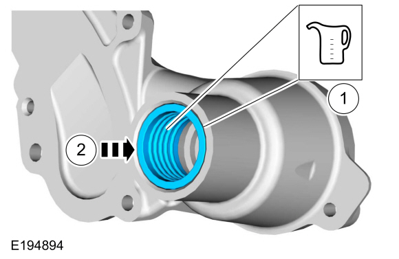
Lubricate the engine front cover bore with clean engine oil.
-
Using the special tools, install the new crankshaft front oil seal.
Use Special Service Tool: 303-335
(T88T-6701-A)
Installer, Front Cover Oil Seal.
, 303-1531
Installer, Front Crank Seal and Damper.
-
Lubricate the crankshaft front seal inner lip with clean engine oil.
-
Lubricate the crankshaft pulley sealing surface with clean engine oil prior to installation.
-
Using the special tools, install the crankshaft pulley.
Use Special Service Tool: 303-335
(T88T-6701-A)
Installer, Front Cover Oil Seal.
, 303-1531
Installer, Front Crank Seal and Damper.
-
NOTE:
Use a universal pulley holder (such as an OTC 4754, or equivalent).
Using a universal pulley holder, install and tighten a new crankshaft pulley bolt.
Torque:
Stage 1:
166 lb.ft (225 Nm)
Stage 2:
Loosen:
360°
Stage 3:
26 lb.ft (35 Nm)
Stage 4:
270°
-
Rotate the crankshaft pulley bolt clockwise to position
the camshaft lobe upward for the camshaft roller follower to be
installed.
-
NOTE:
Do not allow the valve keepers to fall off the valve
or the valve may drop into the cylinder. If a valve drops into the
cylinder, the cylinder head must be removed.
NOTE:
It may be necessary to push the valve down while compressing the spring.
-
Install Special Service Tool: 303-1633
Remover, Roller Rocker Follower.
-
Turn the knob on the special tool clockwise to depress the valve and spring.
-
-
Lubricate the camshaft roller follower with clean engine oil.
-
Install the camshaft roller follower.
-
Turn the knob on the special tool counterclockwise to raise the valve and spring.
Remove Special Service Tool: 303-1633
Remover, Roller Rocker Follower.
-
Repeat steps for the remaining camshaft roller followers.
-
NOTE:
Installation of new seals is only required if damaged seals were removed.
Using the special tools, install new spark plug tube seals.
Use Special Service Tool: 205-153
(T80T-4000-W)
Handle.
, 303-1247
VCT Spark Plug Tube Seal Remover and Installer.
-
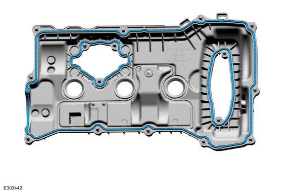
Install new gaskets.
-
NOTICE:
Do not use metal scrapers, wire brushes, power
abrasive discs or other abrasive means to clean the sealing surfaces.
These tools cause scratches and gouges which make leak paths. Use a
plastic scraping tool to remove all traces of old sealant.
Clean the valve cover mating surface of the cylinder head and engine front cover.
Refer to: RTV Sealing Surface Cleaning and Preparation (303-00 Engine System - General Information, General Procedures).
Use the General Equipment: Plastic Scraper
Material: Motorcraft® Silicone Gasket Remover
/ ZC-30-A
Material: Motorcraft® Metal Surface Prep Wipes
/ ZC-31-B
Material: Motorcraft® Metal Brake Parts Cleaner
/ PM-4-A, PM-4-B
.jpg) |
|
-
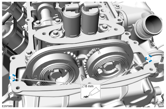
NOTICE:
If the valve cover is not installed and the
fasteners tightened within 10 minutes, the sealant must be removed and
the sealing area cleaned.
Apply an 8 mm (0.31 in) diameter drop of Motorcraft®
High Performance Engine RTV Silicone to the engine front
cover-to-cylinder head joints.
Material: Motorcraft® High Performance Engine RTV Silicone
/ TA-357
(WSE-M4G323-A6)
-
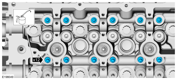
Install the valve cover and tighten the bolts in sequence.
Torque:
89 lb.in (10 Nm)
-
NOTE:
Installation of new seals is only required if damaged seals were removed.
Using the special tools, install new spark plug tube seals.
Use Special Service Tool: 205-153
(T80T-4000-W)
Handle.
, 303-1247
VCT Spark Plug Tube Seal Remover and Installer.
-
Install new gaskets
-
NOTICE:
Do not use metal scrapers, wire brushes, power
abrasive discs or other abrasive means to clean the sealing surfaces.
These tools cause scratches and gouges which make leak paths. Use a
plastic scraping tool to remove all traces of old sealant.
Clean the valve cover mating surface of the cylinder head and engine front cover.
Refer to: RTV Sealing Surface Cleaning and Preparation (303-00 Engine System - General Information, General Procedures).
Use the General Equipment: Plastic Scraper
Material: Motorcraft® Silicone Gasket Remover
/ ZC-30-A
Material: Motorcraft® Metal Surface Prep Wipes
/ ZC-31-B
Material: Motorcraft® Metal Brake Parts Cleaner
/ PM-4-A, PM-4-B
.jpg) |
|
-
NOTICE:
If the valve cover is not installed and the
fasteners tightened within 10 minutes, the sealant must be removed and
the sealing area cleaned.
Apply an 8 mm (0.31 in) diameter drop of Motorcraft®
High Performance Engine RTV Silicone to the engine front
cover-to-cylinder head joints.
Material: Motorcraft® High Performance Engine RTV Silicone
/ TA-357
(WSE-M4G323-A6)
-
Install the valve cover and tighten the bolts in sequence.
Torque:
89 lb.in (10 Nm)
-
Install the bracket and the nuts.
Torque:
53 lb.in (6 Nm)
-
Inspect and replace any ignition coil-on-plugs that have rubber boots with cracks, rips or tears.
-
Install the RH ignition coil-on-plugs and stud bolts.
Torque:
53 lb.in (6 Nm)
-
Install the LH ignition coil-on-plugs and stud bolts.
Torque:
53 lb.in (6 Nm)
-
-
Lubricate the inside and the outside diameter of the grommet with clean engine coolant.
-
Install the grommet so it is flush with the rear of the coolant pump housing.
-
Install a new coolant pump gasket.
-
NOTE:
Verify the front cover dowel pins are aligned to the
coolant pump and that the coolant pump is fully seated prior to
installing the fasteners.
-
Install the coolant pump and the fasteners.
Torque:
Fasteners 1-6:
Stage 1:
89 lb.in (10 Nm)
Stage 2:
45°
-
Torque:
Fastener 7:
18 lb.ft (24 Nm)
-
Torque:
Fasteners 8:
Stage 1:
89 lb.in (10 Nm)
Stage 2:
45°
-
-
Install the coolant pump pulley and the bolts.
Torque:
18 lb.ft (24 Nm)
-
Install the idler pulley and the bolt.
Torque:
35 lb.ft (48 Nm)
-
Install the idler pulley and the bolt.
Torque:
18 lb.ft (24 Nm)
-
Install a new oil cooler gasket.
-
Install the oil cooler and the fasteners.
Torque:
89 lb.in (10 Nm)
-
Install a new fuel rail-to-fuel rail high-pressure fuel tube and finger tighten the flare nuts.
-
Final tighten the flare nuts.
Torque:
Stage 1:
62 lb.in (7 Nm)
Stage 2:
89 lb.in (10 Nm)
Stage 3:
25°
-
Install a new O-ring seal and lubricate with clean engine coolant.
-
-
Install the TC coolant return tube and clamp.
-
Install the bolt.
Torque:
89 lb.in (10 Nm)
-
Inspect the gaskets and install new gaskets as necessary.
-
NOTICE:
Do not use wire brushes, power abrasive discs or 3M™
Roloc® Bristle Disk (2-in white part number 07528) to clean the sealing
surfaces. These tools cause scratches and gouges that make leak paths.
They also cause contamination that will cause premature engine failure.
Remove all traces of the sealant.
Make sure that the mating faces of the engine are clean and free of foreign material.
Refer to: RTV Sealing Surface Cleaning and Preparation (303-00 Engine System - General Information, General Procedures).
Use the General Equipment: Plastic Scraper
Material: Motorcraft® Silicone Gasket Remover
/ ZC-30-A
Material: Motorcraft® Metal Brake Parts Cleaner
/ PM-4-A, PM-4-B
Material: Motorcraft® Metal Surface Prep Wipes
/ ZC-31-B
.jpg) |
|
-
NOTICE:
Failure to use Motorcraft® High Performance Engine
RTV Silicone may cause the engine oil to foam excessively and result in
serious engine damage.
NOTE:
If the brake vacuum pump is not secured within 10
minutes of sealant application, the sealant must be removed and the
sealing area cleaned. Failure to follow this procedure can cause future
oil leakage.
Apply 8 mm (0.31 in) beads of Motorcraft® High Performance Engine RTV Silicone in the locations shown.
Material: Motorcraft® High Performance Engine RTV Silicone
/ TA-357
(WSE-M4G323-A6)
-
NOTE:
Manually align the brake vacuum pump drive key with the camshaft slot before installation.
Position the vacuum pump and install the fasteners.
Torque:
89 lb.in (10 Nm)
-
Install new O-ring seals and lubricate with clean engine coolant.
-
-
Install the TC coolant return tube and clamp.
-
Install the bolt.
Torque:
89 lb.in (10 Nm)
-
-
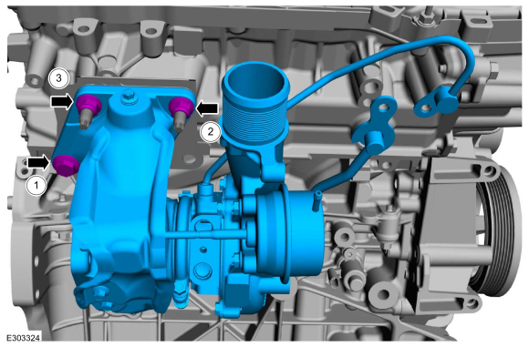
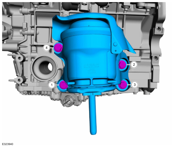
If removed, install new TC mounting studs.
Torque:
102 lb.in (11.5 Nm)
-
-
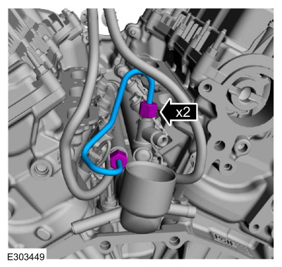
Install new TC oil supply tube O-ring seals and a new TC oil supply tube oil filter. Lubricate the new TC oil supply tube O-ring seals with clean engine oil.
-
Install a new TC coolant supply tube O-ring seal. Lubricate the new TC coolant supply tube O-ring seal with clean engine coolant.
-
-
NOTE:
Install the coolant supply tube and the oil supply tube to the engine block while installing the TC.
Install the TC and loosely install the new fasteners.
-
Tighten the fasteners in sequence.
Torque:
Fastener 1:
44 lb.ft (60 Nm)
Fastener 2:
44 lb.ft (60 Nm)
Fastener 3:
27 lb.ft (37 Nm)
Re-tighten fastener 1:
44 lb.ft (60 Nm)
Re-tighten fastener 2:
44 lb.ft (60 Nm)
Re-tighten fastener 3:
27 lb.ft (37 Nm)
-
-
Install the TC oil supply tube bolt.
Torque:
18 lb.ft (24 Nm)
-
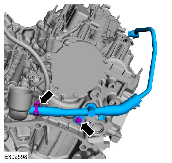
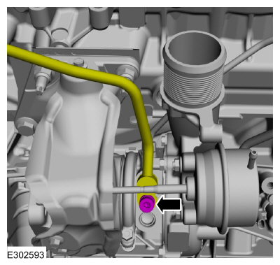
Install the TC coolant supply tube bolt.
Torque:
89 lb.in (10 Nm)
-
Install the TC coolant return tube and the bolt.
Torque:
89 lb.in (10 Nm)
-
Install a new TC oil return tube-to-engine block gasket.
-
Install a new TC oil return tube O-ring seal and lubricate with clean engine oil.
-
Install the TC oil return tube and the fasteners.
Torque:
89 lb.in (10 Nm)
-
If removed, install and tighten the high-pressure fuel pump mounting studs.
Torque:
106 lb.in (12 Nm)
-
NOTICE:
Only rotate the crankshaft Clockwise (CW) or damage to the engine may occur.
NOTICE:
The drive lobe for the high-pressure fuel pump must
be at BDC (bottom dead center) for the high-pressure fuel pump
installation.
Using the crankshaft pulley bolt, turn the crankshaft
until the high-pressure fuel pump drive lobe is at BDC (bottom dead
center).
-
Apply clean engine oil to the high-pressure fuel pump
mounting pedestal bore, the drive lobe and the roller tappet.
-
Install the high-pressure fuel pump roller tappet.
-
NOTE:
Apply clean engine oil to the high-pressure fuel pump O-ring seals.
Install a new high-pressure fuel pump O-ring seal and lubricate with clean engine oil.
-
Install the high-pressure fuel pump, then install the
mounting nuts finger tight. Alternately tighten each high-pressure fuel
pump nut one complete revolution until seated. Tighten the fuel
high-pressure fuel pump nuts in the following 2 stages.
Torque:
Stage 1:
177 lb.in (20 Nm)
Stage 2:
45°
 |
|
-
NOTICE:
In stage 4, if the torque required to tighten any
flare nut on the new high-pressure fuel tube reaches or exceeds 37 lb ft
(50 Nm), then that high pressure fuel tube must be discarded and
replaced with another new high-pressure fuel tube.
NOTE:
Calculate the correct torque wrench setting for the
following torque using the Torque Wrench Adapter Formulas.
NOTE:
Make sure that a new high-pressure fuel tube is installed.
Install the high-pressure fuel tube and bracket nuts,
tighten the high-pressure fuel tube flare nuts and bracket nuts finger
tight.
Torque:
Stage 1:
Tighten the high-pressure fuel tube bracket nuts to :
89 lb.in (10 Nm)
Stage 2:
Tighten the high-pressure fuel tube flare nuts to :
62 lb.in (7 Nm)
Stage 3:
Tighten the high-pressure fuel tube flare nuts to :
89 lb.in (10 Nm)
Stage 4:
Tighten the high-pressure fuel tube flare nuts an additional :
25°
 |
|
-
-
NOTICE:
If the engine is repaired or replaced because of
upper engine failure, typically including valve or piston damage, check
the intake manifold for metal debris. If metal debris is found, install a
new intake manifold. Failure to follow these instructions can result in
engine damage.
Install the intake manifold and tighten the bolts.
Torque:
89 lb.in (10 Nm)
-
Install the coolant pipe and the bolts.
Torque:
97 lb.in (11 Nm)
-
-
Install the vacuum harness onto the engine.
-
Attach the vacuum harness retainers.
-
Install the bolts.
Torque:
62 lb.in (7 Nm)
-
-
Connect the vacuum harness quick release coupling.
Refer to: Quick Release Coupling (310-00A Fuel System - General Information - 3.0L EcoBoost, General Procedures).
-
Attach the vacuum harness retainer.
-
Install the vacuum hose and clamp.
-
-
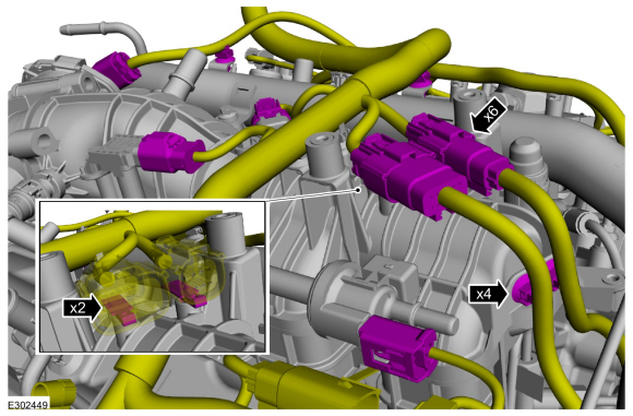
Install the wiring harness onto the engine.
-
Connect the wiring harness electrical connectors.
-
Attach the wiring harness retainers.
-
-
Attach the wiring harness retainers.
-
Connect the wiring harness electrical connectors.
-
-
Attach the wiring harness retainer.
-
Install the ground wire and stud bolt to the rear of the RH cylinder head.
Torque:
89 lb.in (10 Nm)
-
-
Attach the wiring harness retainers.
-
Connect the wiring harness electrical connectors.
-
-
Attach the wiring harness retainers.
-
Connect the wiring harness electrical connectors.
-
-
Connect the CHT electrical connector.
-
Slide the wiring harness insulator down.
-
Install the ground wire and the stud bolt.
Torque:
89 lb.in (10 Nm)
-
Install the crankcase vent tube and connect the quick release couplings.
Refer to: Quick Release Coupling (310-00A Fuel System - General Information - 3.0L EcoBoost, General Procedures).
-
-
Install the CAC inlet pipe and tighten the clamp.
Torque:
42 lb.in (4.8 Nm)
-
Install the bolt.
Torque:
93 lb.in (10.5 Nm)
-
Attach the wiring harness retainer.
-
Install the air cleaner outlet pipe and the bolts.
Torque:
93 lb.in (10.5 Nm)
-
Install the A/C compressor and the bolts.
Torque:
18 lb.ft (25 Nm)
-
-
Install the EVAP tube and connect the quick release coupling.
Refer to: Quick Release Coupling (310-00A Fuel System - General Information - 3.0L EcoBoost, General Procedures).
-
Install the fuel tube assembly and connect the quick release coupling.
Refer to: Quick Release Coupling (310-00A Fuel System - General Information - 3.0L EcoBoost, General Procedures).
-
Attach the fuel tube retainer.
-
Install the oil level indicator.
LHD AWD
-
Install a new front axle assembly seal and lubricate with clean engine oil.
-
-
Clean the front axle assembly-to-cylinder block
mating surfaces of any dirt or foreign material prior to installation.
-
Install the front axle assembly and the bolts.
Torque:
Stage 1:
66 lb.ft (90 Nm)
Stage 2:
90°
-
Install a new axle connector seal and lubricate with clean engine oil.
-
Install the front axle disconnect actuator and the bolts.
Torque:
26 lb.ft (35 Nm)
LHD RWD
-
Install the engine mount spacer and the bolt.
Torque:
Stage 1:
66 lb.ft (90 Nm)
Stage 2:
90°
LHD AWD/LHD RWD
-
Clean the engine mount-to-cylinder block mating surfaces of any dirt or foreign material prior to installation.
-
Position the RH engine mount and install the new studs.
Torque:
35 lb.ft (48 Nm)
-
Install the new bolts and nuts finger-tight and then tighten in sequence.
Torque:
Stage 1:
66 lb.ft (90 Nm)
Stage 2:
90°
-
Clean the engine mount-to-cylinder block mating surfaces of any dirt or foreign material prior to installation.
-
Install the LH engine mount, the new bolts finger-tight and then tighten in sequence.
Torque:
46 lb.ft (63 Nm)
-
Using a floor crane, remove the engine from the mounting stand.
Install Special Service Tool: 303-1634
Lift Eyes (2).
, 303-1246
Engine Spreader Bar.
Use the General Equipment: Floor Crane
Use the General Equipment: Mounting Stand
-
Lubricate the crankshaft rear seal lips with clean engine oil.
.jpg) |
|
-
NOTE:
The crankshaft rear seal and retainer plate must be
installed within 10 minutes of applying the sealer and the bolts must be
installed and tightened to 2-5 Nm (18-44 lb-in) within 15 of applying
the sealer. Final tightening of the bolts must be completed within 60
minutes of applying the sealer. Failure to follow this procedure can
cause future oil leakage.
-
Apply a 4.5 mm (0.18 in) bead of Motorcraft® High
Performance Engine RTV Silicone to the crankshaft rear seal and retainer
plate.
Material: Motorcraft® High Performance Engine RTV Silicone
/ TA-357
(WSE-M4G323-A6)
-
Overlap the beginning and ending of the sealant bead 15 mm (0.59 in).
Material: Motorcraft® High Performance Engine RTV Silicone
/ TA-357
(WSE-M4G323-A6)
-
Apply 9 mm (0.35 in) beads of Motorcraft® High
Performance Engine RTV Silicone that are 10 mm (0.40 in) in length as
indicated in the graphic.
Material: Motorcraft® High Performance Engine RTV Silicone
/ TA-357
(WSE-M4G323-A6)
.jpg) |
|
-
NOTICE:
The special tool must be inserted into the rear of
the crankshaft seal to prevent the seal lip from rolling backwards.
-
Insert the magnetic base of the special tool into the rear opening of the crankshaft seal.
Install Special Service Tool: 303-1250
Seal Installer, Rear Main.
-
The magnetic base of the special tool should protrude slightly from the front of the seal plate
-
-
Position the special tool and seal plate onto the end of the crankshaft.
Use Special Service Tool: 303-1250
Seal Installer, Rear Main.
-
Slide the new crankshaft rear seal and retainer plate onto the crankshaft and into the installed position.
-
Install the crankshaft rear seal retainer plate bolts.
Remove Special Service Tool: 303-1250
Seal Installer, Rear Main.
Torque:
89 lb.in (10 Nm)
-
-
Install the CKP sensor and the stud bolt.
Torque:
89 lb.in (10 Nm)
-
Connect the CKP sensor electrical connector.
-
Install the heat shield and the nut.
Torque:
89 lb.in (10 Nm)
-
Install the crankshaft sensor ring.
-
-
Position the flexplate on the crankshaft.
-
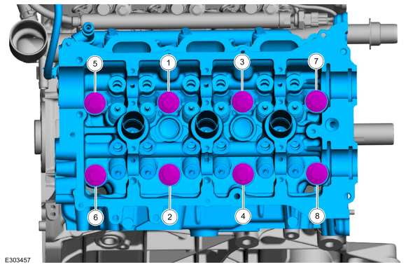
Install the bolts then rundown the bolts one turn at
a time in sequence shown until the flexplate is snug against the rear
face of the crankshaft.
-
Final tighten the bolts in sequence shown.
Torque:
59 lb.ft (80 Nm)
DISASSEMBLY
NOTICE:
The RH and LH pistons are similar in appearance but differ
in design specifications. The pistons must be installed in the correct
cylinder bank or serious damage to the engine will occur...
Special Tool(s) /
General Equipment
303-1246Engine Spreader BarTKIT-2006UF-FLMTKIT-2006UF-ROW
303-1634Lift Eyes (2)TKIT-2014D-ROW3TKIT-2014D-FL_ROW
Adjustable Mounting Arm
Wooden Block
Materials
Name
Specification
Motorcraft® Premium Long-Life GreaseXG-1-E1
ESA-M1C75-B
Motorcraft® MERCON® ULV Automatic Transmission FluidXT-12-QULV
WSS-M2C949-A, MERCON® ULV
NOTICE:
The turbocharger compressor vanes can be damaged by even the
smallest particles...
Other information:
Overview
Item
Description
1
SSC
2
C clutch control valve
3
C clutch latch valve
4
C clutch apply circuit
5
C clutch piston
6
C clutch assembly
7
Ring gear No...
Illuminates when you switch lane
centering on. The color of the
indicator changes to indicate the
system status.
Gray indicates the system is on but inactive.
Green indicates the system is active and
applying assistance steering torque input to
keep your vehicle in the center of the lane...
.jpg)
.jpg)
.jpg)
.jpg)
.jpg)
.jpg)
.jpg)
.jpg)
.jpg)
.jpg)
.jpg)
.jpg)
.jpg)
.jpg)
.jpg)
.jpg)
.jpg)
.jpg)
.jpg)
.jpg)
.jpg)
.jpg)
.jpg)
.jpg)
.jpg)
.jpg)
.jpg)
.jpg)
.jpg)
.jpg)
.jpg)
.jpg)
.jpg)
.jpg)
.jpg)
.jpg)
.jpg)
.jpg)
.jpg)
.jpg)
.jpg)
.jpg)
.jpg)
.jpg)
.jpg)
.jpg)
.jpg)
.jpg)
.jpg)
.jpg)
.jpg)
.jpg)
.jpg)
.jpg)
.jpg)
.jpg)
.jpg)
.jpg)
.jpg)
.jpg)
.jpg)
.jpg)
.jpg)
.jpg)
.jpg)
.jpg)
.jpg)
.jpg)
.jpg)
.jpg)
.jpg)
.jpg)
.jpg)
.jpg)
.jpg)
.jpg)
.jpg)
.jpg)
.jpg)
.jpg)
.jpg)
.jpg)
.jpg)
.jpg)
.jpg)
.jpg)
.jpg)
.jpg)
.jpg)
.jpg)
.jpg)
.jpg)
.jpg)
.jpg)
.jpg)
.jpg)
.jpg)
.jpg)
.jpg)
.jpg)
.jpg)
.jpg)
.jpg)
.jpg)
.jpg)
.jpg)
.jpg)
.jpg)
.jpg)
.jpg)
.jpg)
.jpg)
.jpg)
.jpg)
.jpg)
.jpg)
.jpg)
.jpg)
.jpg)
.jpg)
.jpg)
.jpg)
.jpg)
.jpg)
.jpg)
.jpg)
.jpg)
.jpg)
.jpg)
 Disassembly and Assembly of Subassemblies - Piston
 Installation - Engine