Lincoln Aviator: Automatic Transmission - 10-Speed Automatic Transmission – 10R60 / Description and Operation - A Clutch
Overview
.jpg)
| Item | Description |
| 1 | SSA |
| 2 | A clutch control valve |
| 3 | A clutch latch valve |
| 4 | A clutch apply circuit |
| 5 | A clutch piston |
| 6 | A clutch assembly |
| 7 | Ring gear No. 1 |
Ring gear No. 1 is connected to the A clutch. When the A clutch applies, it holds the ring gear No. 1 stationary.
A Clutch Exploded View
.jpg)
| Item | Description |
| 1 | Front support assembly |
| 2 | A clutch piston |
| 3 | A clutch piston return spring |
| 4 | A clutch wave spring |
| 5 | A clutch apply plate |
| 6 | A clutch steel plates |
| 7 | A clutch friction plates |
| 8 | A clutch separating springs |
| 9 | A clutch pressure plate |
| 10 | Ring gear No. 1 |
| 11 | Transmission case |
A Clutch Hydraulic Circuits
.jpg)
| Item | Description |
| 1 | Line pressure |
| 2 | Pump output |
| 3 | A clutch control valve |
| 4 | SSA |
| 5 | Control pressure to latch valve |
| 6 | A clutch latch valve |
| 7 | Apply pressure to mechanical A clutch |
| 8 | Mechanical A clutch |
| 9 | Elevated exhaust pressure |
| 10 | Clutch exhaust |
A Clutch Hydraulic Operation
Line pressure is supplied to the A clutch control valve and the A clutch latch valve. As SSA turns on, it moves the control valve allowing regulated line pressure to flow to the A clutch latch valve and then to the mechanical A clutch. When the regulated line pressure in the A clutch control circuit reaches approximately 698 kPa (100 psi), the mechanical A clutch is fully applied. The pressure in the A clutch control circuit moves the A clutch latch valve to the left which allows line pressure to hold the mechanical A clutch applied.
A Clutch Hydraulic Passages
.jpg)
.jpg)
.jpg)
 Description and Operation - Transmission Description - System Operation and Component Description
System Diagram
Item
Description
1
SSB
2
SSC
3
SSD
4
SSE
5
SSF
6
LPC
7
TSS
8
ISSB
9
Transmission
10
Transmission
11
TFT
12
TRS
13
SSA
14
PCM
15
TCC
16
OSS
17
ISSA
18
GSM
19
PBW
Network Message Chart
Broadcast Message
Originating Module
Message Purpose
Engine Speed
PCM
Directly affects shift scheduling, TCC control, line pressure and transmission diagnostics...
 Description and Operation - B Clutch
Overview
Item
Description
1
SSB
2
B clutch control valve
3
B clutch latch valve
4
B clutch apply circuit
5
B clutch piston
6
B clutch assembly
7
One-Way Clutch (OWC)
8
Sun gear No...
Other information:
Lincoln Aviator 2020-2026 Service Manual: Description and Operation - D Clutch
Overview Item Description 1 SSD 2 D clutch control valve 3 Clutch gain control valve 4 D clutch apply circuit 5 D clutch piston 6 D clutch assembly 7 Planetary carrier No...
Lincoln Aviator 2020-2026 Service Manual: Specifications
Lubricants, Fluids, Sealants and Adhesives Name Specification Fill Capacity Motorcraft® Yellow Concentrated Antifreeze/CoolantVC-13-G WSS-M97B57-A1 16.4 qt (15.5L) Motorcraft® Yellow Prediluted Antifreeze/CoolantVC-13DL-G WSS-M97B57-A2 16...
Categories
- Manuals Home
- Lincoln Aviator Owners Manual
- Lincoln Aviator Service Manual
- Configuring The Head Up Display
- Tire Change Procedure
- Description and Operation - Jacking and Lifting
- New on site
- Most important about car
Activating Intelligent Access
The intelligent access key must be within 3 ft (1 m) of the door or luggage compartment you intend to lock or unlock.
At a Door
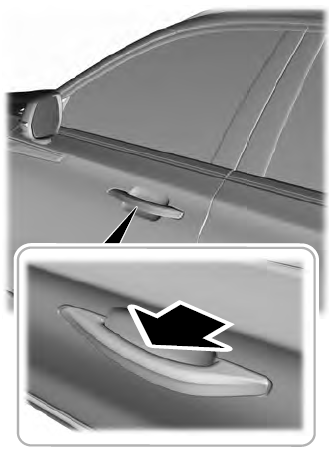
Electronic door handles are on each door. Gently depress the switch inside the exterior door handle to unlock and open the door. An unlock symbol illuminates on the door window trim indicating your vehicle is unlocked.

