Lincoln Aviator: Charging System - General Information / Description and Operation - Charging System - Overview
Overview
The generator is driven by the FEAD belt. When the engine is started, the generator begins to generate AC voltage which is internally converted to DC voltage. The DC voltage level is controlled by the voltage regulator (located on the rear of the generator) and is supplied to the battery.
The PCM controls the voltage regulation setpoint and communicates this information to the generator internal voltage regulator over a LIN communication circuit.
This vehicle is equipped with an Electrical engergy management system (load shed strategy). The BCM monitors the battery state of charge using information from the battery monitoring sensor attached to the negative battery post and manages battery charging.
The PCM monitors the generator current using the generator current sensor attached to the generator B+ battery cable. The information supplied to the PCM from the generator current sensor is used by the PCM to adjust the engine idle stability and torque control.
 Description and Operation - Charging System - System Operation and Component Description
System Operation
System Diagram
Item
Description
1
PCM
2
GWM
3
IPC
4
Generator
5
Generator current sensor
6
HS-CAN1
7
HS-CAN1
8
HS-CAN3
9
BCM
10
Battery monitoring sensor
Network Message Chart
Module Network Input Messages — Body Control Module (BCM)
Broadcast Message
Originating Module
Message Purpose
Alternator fault
PCM
The PCM has detected a fault in the generator or generator circuits...
Other information:
Lincoln Aviator 2020-2026 Service Manual: Specifications
Lubricants, Fluids, Sealers and Adhesives NOTICE: Do not over-lubricate the driveshaft components. Using excessive grease may damage the driveshaft components. NOTE: Wipe off any excess grease. Item Description Specification Rear driveshaft: Front tube plunging splines Material: Motorcraft® Premium Long-Life Grease / XG-1-E1 (ESA-M1C75-B) ESA-M1C75-B Rear driveshaft: Alignment bushing Material: Motorcraft® Premium Long-Life Grease / XG-1-E1 (ESA-M1C75-B) ESA-M1C75-B Rear driveshaft: Rear CV-joint splines Material: Motorcraft® Premium Long-Life Grease / XG-1-E1 (ESA-M1C75-B) ESA-M1C75-B Front driveshaft: Front axle end plug-on yoke splines Material: Slip Yoke Grease / 5L3Z-19A506-A - Front driveshaft: Transfer case output shaft splines Material: Motorcraft® High Temperature 4x4 Front Axle and Wheel Bearing Grease / XG-11 (WSS-M1C267-A1) WSS-M1C267-A1 Front Driveshaft Item 3...
Lincoln Aviator 2020-2026 Service Manual: Removal and Installation - Light Sensor
Removal NOTE: Removal steps in this procedure may contain installation details. Using a non-marring tool release and position the light sensor. Disconnect the electrical connector and remove the light sensor...
Categories
- Manuals Home
- Lincoln Aviator Owners Manual
- Lincoln Aviator Service Manual
- Tire Change Procedure
- Wireless Accessory Charger (If Equipped)
- Child Safety Locks
- New on site
- Most important about car
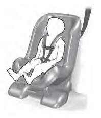
Child Seats

Use a child restraint (sometimes called an infant carrier, convertible seat, or toddler seat) for infants, toddlers and children weighing 40 lb (18 kg) or less (generally four-years-old or younger).
Using Lap and Shoulder Belts
WARNING: Do not place a rearward facing child restraint in front of an active airbag. Failure to follow this instruction could result in personal injury or death.

