Lincoln Aviator: Cruise Control / Description and Operation - Cruise Control - Overview
Overview
The ACC system is controlled by the PCM, CCM and the IPMA.
The ACC modes are selected from the steering wheel mounted switches.
The gap control setting is selected from the lower right steering wheel switch.
ACC gap feature uses radar and camera sensors to adjust vehicle speed to maintain the set gap between the two vehicles in the same lane. Refer to the Owner's Manual for additional information.
The ACC system maintains a selected vehicle speed between 30 kmh (18 mph) and the maximum limited vehicle speed. When a MyKey® restricted key is in use and maxium speed limiter is turned on, vehicle speed is limited to 129 kmh (80 mph).
ACC with stop and go technology allows the vehicle to follow a lead vehicle to a stop. An indicator in the message center indicates the vehicle is in the stopped mode. If the lead vehicle moves from a stop within 3 seconds, the vehicle automatically resumes to the set speed. If the lead vehicle remains stopped for more than 3 seconds, the system resumes when the RESUME switch on the steering wheel is pressed or the operator taps the accelerator pedal.
Intelligent ACC modifies the set speed based on the observed speed limit. When this mode is selected, a bracket appears around the set speed and the detected speed limit sign in the information display. The system is designed to set the vehicle speed to the speed limit detected by the traffic sign recognition system before the vehicle passes the speed limit sign. Refer to the Owner's Manual for additional information.
ACC with lane centering uses radar and camera sensors to keep the vehicle in the lane by applying continuous assistance steering torque input toward the lane centering on highways. Refer to the Owner's Manual for additional information.
 Description and Operation - Cruise Control - System Operation and Component Description
System Operation
Adaptive Cruise Control
Item
Description
1
IPC
2
Accelerator Pedal
3
Deactivator Switch
4
Stoplamp Switch
5
Brake Switch Assembly
6
SCCM
7
PCM
8
Cruise Control Switches
9
IPMA
10
BCM
11
ABS Module
12
GWM
13
RCM
14
CCM
15
SIMA
Network Message Chart
Network Input Messages - ABS Module
Broadcast Message
Originating Module
Message Purpose
ACC deceleration request
IPMA
Used for cruise control automatic braking...
Other information:
Lincoln Aviator 2020-2026 Service Manual: Description and Operation - Supplemental Climate Control - Component Location
3.0L Ecoboost Item Description 1 Cabin heater coolant pump 3.0L Ecoboost - Hybrid Item Description 1 Cabin heater coolant pump 2 Cabin heater coolant diverter valve 3 Cabin heater coolant temperature sensor 4 Cabin coolant heater 3...
Lincoln Aviator 2020-2026 Owners Manual: Using All-Wheel Drive
WARNING: Vehicles with a higher center of gravity (utility and four-wheel drive vehicles) handle differently than vehicles with a lower center of gravity (passenger cars). Avoid sharp turns, excessive speed and abrupt steering in these vehicles...
Categories
- Manuals Home
- Lincoln Aviator Owners Manual
- Lincoln Aviator Service Manual
- Changing the Front Wiper Blades - Vehicles With: Heated Wiper Blades
- Child Safety Locks
- Wireless Accessory Charger (If Equipped)
- New on site
- Most important about car
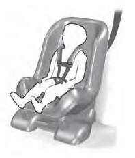
Child Seats

Use a child restraint (sometimes called an infant carrier, convertible seat, or toddler seat) for infants, toddlers and children weighing 40 lb (18 kg) or less (generally four-years-old or younger).
Using Lap and Shoulder Belts
WARNING: Do not place a rearward facing child restraint in front of an active airbag. Failure to follow this instruction could result in personal injury or death.

