Lincoln Aviator: Front Seats / Removal and Installation - Front Seat
Removal
.jpg) WARNING:
The following procedure describes critical repair steps
required for correct seat component installation. Follow all notes and
steps carefully. Do not place any objects between the seat components
and the body of the vehicle, nor any objects within a joint internal to
the seat structure. Failure to follow step instructions may result in
incorrect operation of the seat components and increases the risk of
serious personal injury.
WARNING:
The following procedure describes critical repair steps
required for correct seat component installation. Follow all notes and
steps carefully. Do not place any objects between the seat components
and the body of the vehicle, nor any objects within a joint internal to
the seat structure. Failure to follow step instructions may result in
incorrect operation of the seat components and increases the risk of
serious personal injury.
NOTE: Removal steps in this procedure may contain installation details.
NOTE: Driver seat shown, passenger seat similar.
-
Move the seat to the full upward position and forward or rearward to access all the front seat bolts.
.jpg) |
-
Depower the SRS.
Refer to: Supplemental Restraint System (SRS) Depowering (501-20B Supplemental Restraint System, General Procedures).
-
Disconnect the front seat harness electrical connector.
-
Disconnect the electrical connector.
-
Detach the wiring harness retainer.
-
Disconnect the electrical connector.
.jpg) |
-
Remove the front seat bolt covers.
.jpg) |
-
Remove the front seat.
-
Remove and discard the bolts.
-
Remove and discard the bolts.
.jpg) |
Installation
-
To install, reverse the removal procedure.
-
Install the front seat bolts in the following sequence.
-
Install the front inboard bolt.
Torque: 35 lb.ft (47 Nm)
-
Install the front outboard bolt.
Torque: 35 lb.ft (47 Nm)
-
Install the rear inboard bolt.
Torque: 35 lb.ft (47 Nm)
-
Install the rear outboard bolt.
Torque: 35 lb.ft (47 Nm)
-
Install the front inboard bolt.
.jpg) |
-
Repower the SRS.
Refer to: Supplemental Restraint System (SRS) Repowering (501-20B Supplemental Restraint System, General Procedures).
 Removal and Installation - Front Head Restraint Guide Sleeve
Removal
NOTE:
Driver seat shown, passenger seat similar.
Remove the front seat.
Refer to: Front Seat (501-10A Front Seats, Removal and Installation)...
 Removal and Installation - Front Seat Backrest
Removal
WARNING:
The following procedure describes critical repair steps
required for correct seat component installation. Follow all notes and
steps carefully...
Other information:
Lincoln Aviator 2020-2026 Service Manual: Diagnosis and Testing - Body Control Module C (BCMC)
Diagnostic Trouble Code (DTC) Chart Diagnostics in this manual assume a certain skill level and knowledge of Ford-specific diagnostic practices. REFER to: Diagnostic Methods (100-00 General Information, Description and Operation). Diagnostic Trouble Code Chart Module DTC Description Action BCMC U0100:87 Lost Communication With ECM/PCM "A": Missing Message GO to Pinpoint Test A BCMC U0111:87 Lost Communication With Battery Energy Control Module "A": Missing Message GO to Pinpoint Test B BCMC U0140:87 Lost Communication With Body Control Module: Missing Message GO to Pinpoint Test C BCMC U0164:87 Lost Communication With HVAC Control Module: Missing Message GO to Pinpoint Test D BCMC U024D:87 Lost Communication With "Seat Control Module J": Missing Message GO to Pinpoint Test E BCMC U0293:87 Lost Communication With Hybrid/EV Powertrain Control Module: Missing Message GO to Pinpoint Test F BCMC U1000:00 Solid State Driver Protection Active: Driver Disabled: No Sub Type Information GO to Pinpoint Test G BCMC U2100:00 Initial Configuration Not Complete: No Sub Type Information GO to Pinpoint Test H BCMC U2200:00 Control Module Configuration Memory Corrupt: No Sub Type Information GO to Pinpoint Test H BCMC U3000:49 Control Module: Internal Electronic Failure GO to Pinpoint Test I BCMC U3003:16 Battery Voltage: Circuit Voltage Below Threshold GO to Pinpoint Test J BCMC U3003:17 Battery Voltage: Circuit Voltage Above Threshold GO to Pinpoint Test K Pinpoint Tests PINPOINT TEST A : U0100:87 Refer to Wiring Diagrams Cell 14 for schematic and connector information...
Lincoln Aviator 2020-2026 Service Manual: Removal and Installation - Evaporative Emission Canister
Removal WARNING: Do not smoke, carry lighted tobacco or have an open flame of any type when working on or near any fuel-related component. Highly flammable mixtures may be present and may be ignited. Failure to follow these instructions may result in serious personal injury...
Categories
- Manuals Home
- Lincoln Aviator Owners Manual
- Lincoln Aviator Service Manual
- Description and Operation - Jacking and Lifting
- Resetting the System
- Tire Change Procedure
- New on site
- Most important about car
Activating Intelligent Access
The intelligent access key must be within 3 ft (1 m) of the door or luggage compartment you intend to lock or unlock.
At a Door
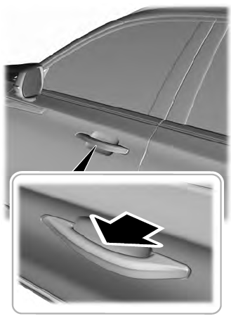
Electronic door handles are on each door. Gently depress the switch inside the exterior door handle to unlock and open the door. An unlock symbol illuminates on the door window trim indicating your vehicle is unlocked.

