Lincoln Aviator 2020-2026 Service Manual / Powertrain / Automatic Transmission / Automatic Transmission - 10-Speed Automatic Transmission – 10R60 / Description and Operation - Low One-Way Clutch Assembly
Lincoln Aviator: Automatic Transmission - 10-Speed Automatic Transmission – 10R60 / Description and Operation - Low One-Way Clutch Assembly
One-Way Clutch (OWC) Exploded View
.jpg)
| Item | Description |
| 1 | Front support assembly |
| 2 | One-Way Clutch (OWC) |
| 3 | Sun gear No. 1 |
| 4 | Sun gear No. 2 |
One-Way Clutch (OWC) Mechanical Operation
.jpg)
The One-Way Clutch (OWC) is a brake clutch that holds the sun gears No. 1 and 2 in one direction and allows it to freewheel in the opposite direction eliminating engine braking in 1st gear when the transmission is in drive. The rollers of the OWC lock to a inner race that is part of the front support assembly.
-
One-Way Clutch (OWC) rollers
-
One-Way Clutch (OWC) inner race
 Description and Operation - F Clutch
Overview
Item
Description
1
SSF
2
F clutch control valve
3
F clutch latch valve
4
F clutch apply circuit
5
F clutch piston
6
F clutch assembly
7
Ring gear No...
 Description and Operation - Main Control Valve Body
Item
Description
1
Internal wiring harness retaining bolt
2
Internal wiring harness
3
Park lock pawl solenoid
4
Solenoid retaining plate bolts
5
Solenoid retaining plate
6
TCC solenoid
7
LPC solenoid
8
Shift solenoid retaining plate bolts
9
Shift solenoid retaining plate
10
SSD
11
SSE
12
SSB
13
SSC
14
SSF
15
SSA
16
TFT
17
Valve channel plate bolts
18
Valve channel plate
19
Lower-to-upper valve body bolts
20
Lower valve body
21
Upper valve body
22
Valve body dowel pins
Lower Valve Body
1
Valve body separator plate bolts
2
Valve body separator plate
3
TCC damper
4
LPC damper assembly
5
Check valve assemblies
6
Check balls (quantity 5)
7
LPC anti-backflow valve assembly
8
TCC priority valve assembly
9
Park lock pawl valve
10
A clutch control valve
11
SSA
12
F clutch control valve
13
SSF
14
C clutch control valve
15
SSC
16
B clutch control valve
17
SSB
18
E clutch control valve
19
SSE
20
D clutch control valve
21
SSD
22
Shift solenoid retainers
Upper Valve Body
1
Lube control valve assembly
2
Plug and spring assembly
3
C clutch latch valve assembly
4
B clutch latch valve assembly
5
F clutch latch valve assembly
6
A clutch latch valve assembly
7
Plug and spring assembly
8
TCC regulator valve assembly
9
Main regulator valve assembly
The main control consists of a upper and lower valve body with solenoids that are controlled by a remote mounted TCM or the PCM...
Other information:
Lincoln Aviator 2020-2026 Service Manual: Description and Operation - Airbag and Seatbelt Pretensioner Supplemental Restraint System (SRS) - Component Location
..
Lincoln Aviator 2020-2026 Owners Manual: Adjusting the Pre-Collision Assist Settings
You can adjust the following settings by using the information display controls. You can change Alert and Distance Alert sensitivity to one of three possible settings. You can switch Distance Indication and Alert on or off. If required, you can switch Active Braking on or off...
Categories
- Manuals Home
- Lincoln Aviator Owners Manual
- Lincoln Aviator Service Manual
- Description and Operation - Body and Frame
- USB Port and Power Point Locations
- Resetting the System
- New on site
- Most important about car
Child Safety Locks
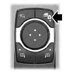
When the child safety locks are set, you cannot open the rear doors from the inside.

The child safety lock control is on the driver door.
Press the control to switch the child safety locks on. Press the control again to switch them off. A light on the child safety control illuminates when you switch them on.
Copyright © 2026 www.liaviator2.com
