Lincoln Aviator 2020-2023 Service Manual / Electrical / Lighting / Exterior Lighting / Diagnosis and Testing - Reversing Lamps

Lincoln Aviator: Exterior Lighting / Diagnosis and Testing - Reversing Lamps

Diagnostic Trouble Code (DTC) Chart

Diagnostics in this manual assume a certain skill level and knowledge of Ford-specific diagnostic practices.
REFER to: Diagnostic Methods (100-00 General Information, Description and Operation).


  Diagnostic Trouble Code Chart


Module   DTC Description Action
  BCM B1277:11 Reverse Lamp: Circuit Short To Ground   GO to Pinpoint Test A
  BCM B1277:15 Reverse Lamp: Circuit Short To Battery or Open   GO to Pinpoint Test A

Symptom Charts

Diagnostics in this manual assume a certain skill level and knowledge of Ford-specific diagnostic practices.
REFER to: Diagnostic Methods (100-00 General Information, Description and Operation).

Symptom Chart: Reversing Lamps


Condition Possible Sources Actions
A module does not respond to the diagnostic scan tool
  • Fuse
  • Wiring, terminals or connectors
  • Module
 
REFER to: Communications Network (418-00 Module Communications Network, Diagnosis and Testing).
Both reversing lamps are inoperative or always on Refer to the Pinpoint Test   GO to Pinpoint Test A
An individual reversing lamp is inoperative Reversing lamp INSTALL a new reversing lamp.
REFER to: Reversing Lamp (417-01 Exterior Lighting, Removal and Installation).

Pinpoint Tests


PINPOINT TEST A : BOTH REVERSING LAMPS ARE INOPERATIVE OR ALWAYS ON

Refer to Wiring Diagrams Cell 93 for schematic and connector information.

Normal Operation and Fault Conditions

REFER to: Exterior Lighting - Overview (417-01 Exterior Lighting, Description and Operation).
REFER to: Exterior Lighting - System Operation and Component Description (417-01 Exterior Lighting, Description and Operation).

DTC Fault Trigger Conditions

DTC Description Fault Trigger Condition
BCM B1277:11 Reverse Lamp: Circuit Short To Ground A continuous memory and on-demand DTC that sets when the BCM detects a short to ground from the reversing lamps output circuit.
BCM B1277:15 Reverse Lamp: Circuit Short To Battery Or Open A continuous memory and on-demand DTC that sets when the BCM detects an open or short to voltage from the reversing lamps output circuit.

Possible Sources

  • Wiring, terminals or connectors
  • Gear range concern
  • BCM
A1 CHECK THE PCM (POWERTRAIN CONTROL MODULE) TRANSMISSION RANGE PID (PARAMETER IDENTIFICATION)
  • Apply the parking brake.
  • Ignition ON.
  • Access the  PCM  and monitor the  TR_CORRECTED  PID

  • Place the gear selector in each gear.

Does the PID indicate the correct value in each gear selection?
Yes If both reverse lamps are inoperative, GO to A2
If both reverse lamps are always on, GO to A5
No DIAGNOSE the transmission range concern.
REFER to: Diagnosis By Symptom (307-01A Automatic Transmission - 10-Speed Automatic Transmission – 10R60, Diagnosis and Testing).

A2 CHECK THE REVERSING LAMP VOLTAGE CIRCUIT FOR A SHORT TO GROUND
  • Place the gear selector in PARK (P).
  • Ignition OFF.
  • Disconnect: Inline (reversing lamp assembly) C424M.
  • Disconnect: BCM C2280C.
  • Measure:
    Click to display connectors
    Positive Lead Measurement / Action Negative Lead
      C2280C-11   Ground

Is the resistance greater than 10,000 ohms?
Yes GO to A3
No REPAIR the circuit in question. After the repair:
If no Diagnostic Trouble Codes (DTCs) are present, TEST the system for normal operation.
If DTC U1000:00 is present, CLEAR the Diagnostic Trouble Codes (DTCs) and REPEAT the self-test (required to enable the lamp output driver if DTC U1000:00 is present).
If DTC U3000:49 is present, INSTALL a new BCM.
REFER to: Body Control Module (BCM) (419-10 Multifunction Electronic Modules, Removal and Installation).

A3 CHECK THE REVERSING OUTPUT CIRCUIT FOR A SHORT TO GROUND
  • Place the gear selector in PARK (P).
  • Ignition OFF.
  • Disconnect: BCM C2280G.
  • Disconnect: Auto-Dimming Interior Mirror C911.
  • Disconnect: BCMC C1035B (if equipped with towing package).
  • Measure:
    Click to display connectors
    Positive Lead Measurement / Action Negative Lead
      C2280G-19   Ground

Is the resistance greater than 10,000 ohms?
Yes GO to A4
No REPAIR the circuit in question. After the repair:
If no Diagnostic Trouble Codes (DTCs) are present, TEST the system for normal operation.
If DTC U1000:00 is present, CLEAR the Diagnostic Trouble Codes (DTCs) and REPEAT the self-test (required to enable the lamp output driver if DTC U1000:00 is present).
If DTC U3000:49 is present, INSTALL a new BCM.
REFER to: Body Control Module (BCM) (419-10 Multifunction Electronic Modules, Removal and Installation).

A4 CHECK THE REVERSING LAMP VOLTAGE CIRCUIT FOR AN OPEN
  • Measure:
    Click to display connectors
    Positive Lead Measurement / Action Negative Lead
      C424M-2   C2280C-11

Is the resistance less than 3 ohms?
Yes GO to A7
No REPAIR the circuit in question.

A5 CHECK THE REVERSING LAMP VOLTAGE SUPPLY CIRCUIT FOR A SHORT TO VOLTAGE
  • Ignition OFF.
  • Disconnect: BCM C2280C.
  • Ignition ON.

Are the reverse lamps still on?
Yes REPAIR the circuit.
No GO to A6

A6 CHECK THE REVERSING OUTPUT SUPPLY CIRCUIT FOR A SHORT TO VOLTAGE
  • Ignition OFF.
  • Connect: BCM C2280C.
  • Disconnect: BCM C2280G.
  • Disconnect: Auto-Dimming Interior Mirror C9012.
  • Disconnect: BCMC C1035B (if equipped with towing package).
  • Ignition ON.
  • Measure:
    Click to display connectors
    Positive Lead Measurement / Action Negative Lead
      C2280G-19   Ground

Is any voltage present?
Yes REPAIR the circuit.
No GO to A7

A7 CHECK FOR CORRECT BCM (BODY CONTROL MODULE) OPERATION
  • Disconnect and inspect all BCM connectors.
  • Repair:
    • corrosion (install new connector or terminals – clean module pins)
    • damaged or bent pins – install new terminals/pins
    • pushed-out pins – install new pins as necessary
  • Reconnect the BCM connectors. Make sure they seat and latch correctly.
  • Operate the system and determine if the concern is still present.

Is the concern still present?
Yes CHECK OASIS for any applicable service articles: TSB, GSB, SSM or FSA. If a service article exists for this concern, DISCONTINUE this test and FOLLOW the service article instructions. If no service articles address this concern,
REFER to: Body Control Module (BCM) (419-10 Multifunction Electronic Modules, Removal and Installation).
No The system is operating correctly at this time. The concern may have been caused by module connections. ADDRESS the root cause of any connector or pin issues.


    Diagnosis and Testing - Parking, Rear and License Plate Lamps

    Diagnostic Trouble Code (DTC) Chart Diagnostics in this manual assume a certain skill level and knowledge of Ford-specific diagnostic practices. REFER to: Diagnostic Methods (100-00 General Information, Description and Operation)...

    Diagnosis and Testing - Stoplamps

    Diagnostic Trouble Code (DTC) Chart Diagnostics in this manual assume a certain skill level and knowledge of Ford-specific diagnostic practices. REFER to: Diagnostic Methods (100-00 General Information, Description and Operation)...

    Other information:

    Lincoln Aviator 2020-2023 Service Manual: Diagnosis and Testing - Instrumentation, Message Center and Warning Chimes


    Diagnostic Trouble Code (DTC) Chart Diagnostics in this manual assume a certain skill level and knowledge of Ford-specific diagnostic practices. REFER to: Diagnostic Methods (100-00 General Information, Description and Operation).   Diagnostic Trouble Code Chart Module   DTC Description Action   ABS C0049:01 Brake Fluid Level:General Electrical Failure   GO to Pinpoint Test L   ABS C0049:7B Brake Fluid Level:Low Fluid Level   GO to Pinpoint Test L   IPC P0460:11 Fuel Level Sensor "A" Circuit:Circuit Short To Ground   GO to Pinpoint Test D   IPC P0460:13 Fuel Level Sensor "A" Circuit:Circuit Open   GO to Pinpoint Test D   IPC U0100:00 Lost Communication With ECM/PCM "A":No Sub Type Information   GO to Pinpoint Test CC   IPC U0103:00 Lost Communication With Gear Shift Control Module A:No Sub Type Information   GO to Pinpoint Test CE   IPC U0111:00 Lost Communication With Battery Energy Control Module "A":No Sub Type Information   GO to Pinpoint Test CF   IPC U0121:00 Lost Communication With Anti-Lock Brake System (ABS) Control Module: No Sub Type Information   GO to Pinpoint Test CG   IPC U013F:00 Lost Communication With Pedestrian Alert Control Module:No Sub Type Information   GO to Pinpoint Test CI   IPC U0140:00 Lost Communication With Body Control Module: No Sub Type Information   GO to Pinpoint Test CJ   IPC U0151:00 Lost Communication With Restraints Control Module: No Sub Type Information   GO to Pinpoint Test CM   IPC U0158:00 Lost Communication With Head Up Display:No Sub Type Information   GO to Pinpoint Test CN   IPC U0159:00 Lost Communication With Parking Assist Control Module "A": No Sub Type Information   GO to Pinpoint Test CP   IPC U0193:00 Lost Communication With "Digital Audio Control Module A": No Sub Type Information   GO to Pinpoint Test CQ   IPC U0199:00 Lost Communication With "Door Control Module A":No Sub Type Information   GO to Pinpoint Test CR   IPC U0212:00 Lost Communication With Steering Column Control Module: No Sub Type Information   GO to Pinpoint Test CS   IPC U0212:82 Lost Communication With Steering Column Control Module:Alive/Sequence Counter Incorrect/Not Updated   GO to Pinpoint Test CS   IPC U0232:00 Lost Communication With Side Obstacle Detection Control Module - Left: No Sub Type Information   GO to Pinpoint Test CU   IPC U0233:00 Lost Communication With Side Obstacle Detection Control Module - Right: No Sub Type Information   GO to Pinpoint Test CU   IPC U023A:00 Lost Communication With Image Processing Module A: No Sub Type Information   GO to Pinpoint Test CW   IPC U023B:82 Lost Communication With Image Processing Module B:Alive/Sequence Counter Incorrect/Not Updated   GO to Pinpoint Test CX   IPC U0241:00 Lost Communication With Headlamp Control Module "A":No Sub Type Information   GO to Pinpoint Test CY   IPC U0253:00 Lost Communication With Accessory Protocol Interface Module:No Sub Type Information   GO to Pinpoint Test CZ   IPC U0260:00 Lost Communication With Seat Control Switch Module "A":No Sub Type Information   GO to Pinpoint Test DA   IPC U0293:00 Lost Communication with Hybrid/EV Powertrain Control Module:No Sub Type Information   GO to Pinpoint Test CD   IPC U0293:82 Lost Communication with Hybrid/EV Powertrain Control Module:Alive/Sequence Counter Incorrect/Not Updated   GO to Pinpoint Test CD   IPC U0401:00 Invalid Data Received from ECM/PCM A:No Sub Type Information   GO to Pinpoint Test CC   IPC U0401:81 Invalid Data Received from ECM/PCM A:Invalid Serial Data Received   GO to Pinpoint Test CC   IPC U0401:82 Invalid Data Received from ECM/PCM A:Alive/Sequence Counter Incorrect/Not Updated   GO to Pinpoint Test CC   IPC U0401:86 Invalid Data Received from ECM/PCM A:Signal Invalid   GO to Pinpoint Test CC   IPC U0405:56 Invalid Data Received From Cruise Control Module:Invalid/Incompatible Configuration   GO to Pinpoint Test CK   IPC U0412:86 Invalid Data Received From Battery Energy Control Module "A":Signal Invalid   GO to Pinpoint Test CF   IPC U0415:00 Invalid Data Received From Anti-Lock Brake System (ABS) Module: No Sub Type Information   GO to Pinpoint Test CG   IPC U0415:82 Invalid Data Received from Anti-Lock Brake System (ABS) Control Module "A":Alive/Sequence Counter Incorrect/Not Updated   GO to Pinpoint Test CG   IPC U0420:82 Invalid Data Received from Power Steering Control Module "A":Alive/Sequence Counter Incorrect/Not Updated   GO to Pinpoint Test CH   IPC U0422:00 Invalid Data Received From Body Control Module:No Sub Type Information   GO to Pinpoint Test CJ   IPC U0424:80 Invalid Data Received From HVAC Control Module:ISO/SAE Reserved   GO to Pinpoint Test CL   IPC U0424:81 Invalid Data Received From HVAC Control Module:Invalid Serial Data Received   GO to Pinpoint Test CL   IPC U0424:82 Invalid Data Received From HVAC Control Module:Alive/Sequence Counter Incorrect/Not Updated   GO to Pinpoint Test CL   IPC U0431:82 Invalid Data Received From Body Control Module "A":Alive/Sequence Counter Incorrect/Not Updated   GO to Pinpoint Test CJ   IPC U0452:81 Invalid Data Received From Restraints Control Module:Invalid Serial Data Received   GO to Pinpoint Test CM   IPC U045A:82 Invalid Data Received From Parking Assist Control Module "A":Alive/Sequence Counter Incorrect/Not Updated   GO to Pinpoint Test CP   IPC U049C:82 Invalid Data Received From Battery Charger Control Module "A":Alive/Sequence Counter Incorrect/Not Updated   GO to Pinpoint Test CO   IPC U0531:82 Invalid Data Received From Rear Gate Module:Alive/Sequence Counter Incorrect/Not Updated   GO to Pinpoint Test CT   IPC U0533:00 Invalid Data Received From Side Obstacle Detection Control Module-Left: No Sub Type information   GO to Pinpoint Test CU   IPC U0533:56 Invalid Data Received From Side Obstacle Detection Control Module "A":Invalid/Incompatible Configuration   GO to Pinpoint Test CV   IPC U0534:00 Invalid Data Received From Side Obstacle Detection Control Module-Right: No Sub Type Information   GO to Pinpoint Test CU   IPC U0534:56 Invalid Data Received From Side Obstacle Detection Control Module "B":Invalid/Incompatible Configuration   GO to Pinpoint Test CV   IPC U0542:82 Invalid Data Received From Headlamp Control Module "A":Alive/Sequence Counter Incorrect/Not Updated   GO to Pinpoint Test CY   IPC U0594:86 Invalid Data Received From Hybrid/EV Powertrain Control Module:Signal Invalid   GO to Pinpoint Test CD   IPC U2100:00 Initial Configuration Not Complete:No Sub Type Information   GO to Pinpoint Test DB   IPC U3000:04 Control Module:System Internal Failures   GO to Pinpoint Test DC   IPC U3000:46 Control Module:Calibration/Parameter Memory Failure   GO to Pinpoint Test DC   IPC U3003:16 Battery Voltage: Circuit Voltage Below Threshold   GO to Pinpoint Test DE   IPC U3003:17 Battery Voltage: Circuit Voltage Above Threshold   GO to Pinpoint Test DF   IPC U300A:64 Ignition Switch:Signal Plausibility Failure   GO to Pinpoint Test DD   PCM P0461:00 Fuel Level Sensor "A" Circuit Range/Performance:No Sub Type Information   GO to Pinpoint Test D   PCM P0462:00 Fuel Level Sensor "A" Circuit Low:No Sub Type Information   GO to Pinpoint Test D   PCM P0463:00 Fuel Level Sensor "A" Circuit High:No Sub Type Information   GO to Pinpoint Test D   PCM P0522:00 Engine Oil Pressure Sensor/Switch "A" Circuit Low:No Sub Type Information   GO to Pinpoint Test W   PCM P0523:00 Engine Oil Pressure Sensor/Switch "A" Circuit High:No Sub Type Information   GO to Pinpoint Test W   PCM P25B0:00 Fuel Level Sensor "A" Stuck:No Sub Type Information   GO to Pinpoint Test D   SIMA B1380:4A Steering Wheel Right Switch Pack:Incorrect Component Installed   GO to Pinpoint Test AG   SIMA B1380:71 Steering Wheel Right Switch Pack:Actuator Stuck   GO to Pinpoint Test AG Symptom Chart(s) Symptom Chart: Instrument Panel Cluster (IPC) Diagnostics in this manual assume a certain skill level and knowledge of Ford-specific diagnostic practices...

    Lincoln Aviator 2020-2023 Service Manual: General Procedures - Wheel to Hub Runout Minimization


    Check NOTE: Wheel-to-hub optimization is important. Clearance between the wheel and hub can be used to offset or neutralize the Road Force® or run-out of the wheel and tire assembly. For every 0.001 inch of wheel-to-hub clearance, the Road Force® can be affected between 1 and 3 pounds depending on the tire stiffness...

    Categories

    Child Safety Locks

    When the child safety locks are set, you cannot open the rear doors from the inside.
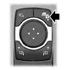
    Lincoln Aviator. Child Safety Locks

    The child safety lock control is on the driver door.

    Press the control to switch the child safety locks on. Press the control again to switch them off. A light on the child safety control illuminates when you switch them on.

    read more

     
    Copyright © 2023 www.liaviator2.com